Delta sigma modulator analog-to-digital converters with quantizer output prediction and comparator reduction
- Summary
- Abstract
- Description
- Claims
- Application Information
AI Technical Summary
Benefits of technology
Problems solved by technology
Method used
Image
Examples
Embodiment Construction
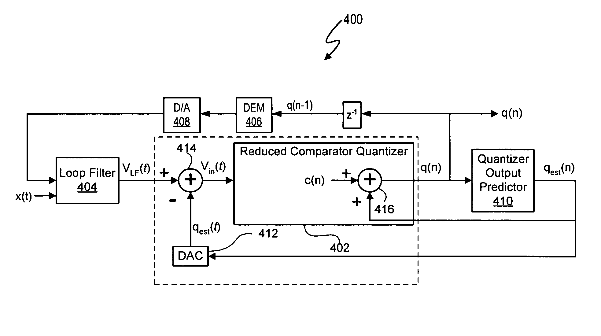
[0031] The quantizers of delta sigma modulators in the signal processing systems described herein use a reduced set of comparators for quantization by predetermining and maintaining a maximum per cycle deviation d between a loop filter output signal VLF(t) and a predicted quantizer output signal qest. In at least one embodiment, a maximum quantizer level deviation d is defined in terms of a number of quantization levels. Thus, the number of comparators in a quantizer needed to quantize the quantizer input signal Vin(t) is based on the maximum quantizer level deviation d.
[0032] In at least one embodiment, the predicted quantizer output signal qest is based on previous quantizer output signals. The predicted quantizer output signal qest is effectively subtracted from the loop filter output signal VLF(t) to generate a quantizer input signal Vin(t). In at least one embodiment, the predicted quantizer output signal qest is designed to ensure that the resulting quantizer input signal Vin...
PUM
 Abstract
Description
Claims
Application Information
 - R&D
- Intellectual Property
- Life Sciences
- Materials
- Tech Scout
- Unparalleled Data Quality
- Higher Quality Content
- 60% Fewer Hallucinations
Browse by: Latest US Patents, China's latest patents, Technical Efficacy Thesaurus, Application Domain, Technology Topic, Popular Technical Reports.
© 2025 PatSnap. All rights reserved.Legal|Privacy policy|Modern Slavery Act Transparency Statement|Sitemap|About US| Contact US: help@patsnap.com


