Polarizing Plate Provided With Optical Compensation Layers and Image Display Apparatus Using the Same

a technology of optical compensation and polarizing plate, applied in the direction of polarising elements, optics, instruments, etc., can solve the problems of black display light leakage and contrast reduction that have not been solved, and achieve the effect of reducing the thickness of an image display apparatus, improving the light leakage of black display, and reducing the thickness of the display

Active Publication Date: 2007-09-27
NITTO DENKO CORP
View PDF17 Cites 19 Cited by
  • Summary
  • Abstract
  • Description
  • Claims
  • Application Information

AI Technical Summary

Benefits of technology

[0014] As described above, according to the present invention, the angle formed between the absorption axis of the polarizer and the slow axis of each of the first optical compensation layer (λ / 2 plate), the second optical compensation layer (λ / 4 plate), and the third optical compensation layer (negative C plate) is set within a predetermined range, to thereby significantly improve light leak in black display in a reflective and semi-transmissive liquid crystal display apparatus of VA mode, in particular. The third optical compensation layer (negative C plate) is formed of a cholesteric alignment fixed layer by using a liquid crystal material and a chiral agent, to thereby drastically reduce its thickness compared with that of a conventional negative C plate. As a result, the present invention may greatly contribute to reduction in thickness of an image display apparatus. Further, by reducing the thickness of the third optical compensation layer (negative C plate), uneven display due to heat may be significantly prevented.

Problems solved by technology

However, in a conventional reflective or semi-transmissive liquid crystal display apparatus of VA mode, problems of light leak in black display and reduction in contrast have not been solved for a long period of time.

Method used


Image

  • Polarizing Plate Provided With Optical Compensation Layers and Image Display Apparatus Using the Same
  • Polarizing Plate Provided With Optical Compensation Layers and Image Display Apparatus Using the Same
  • Polarizing Plate Provided With Optical Compensation Layers and Image Display Apparatus Using the Same

Examples


example 1

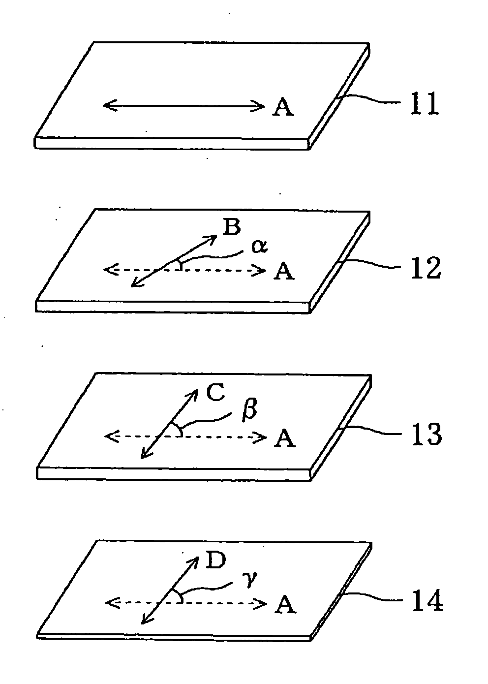
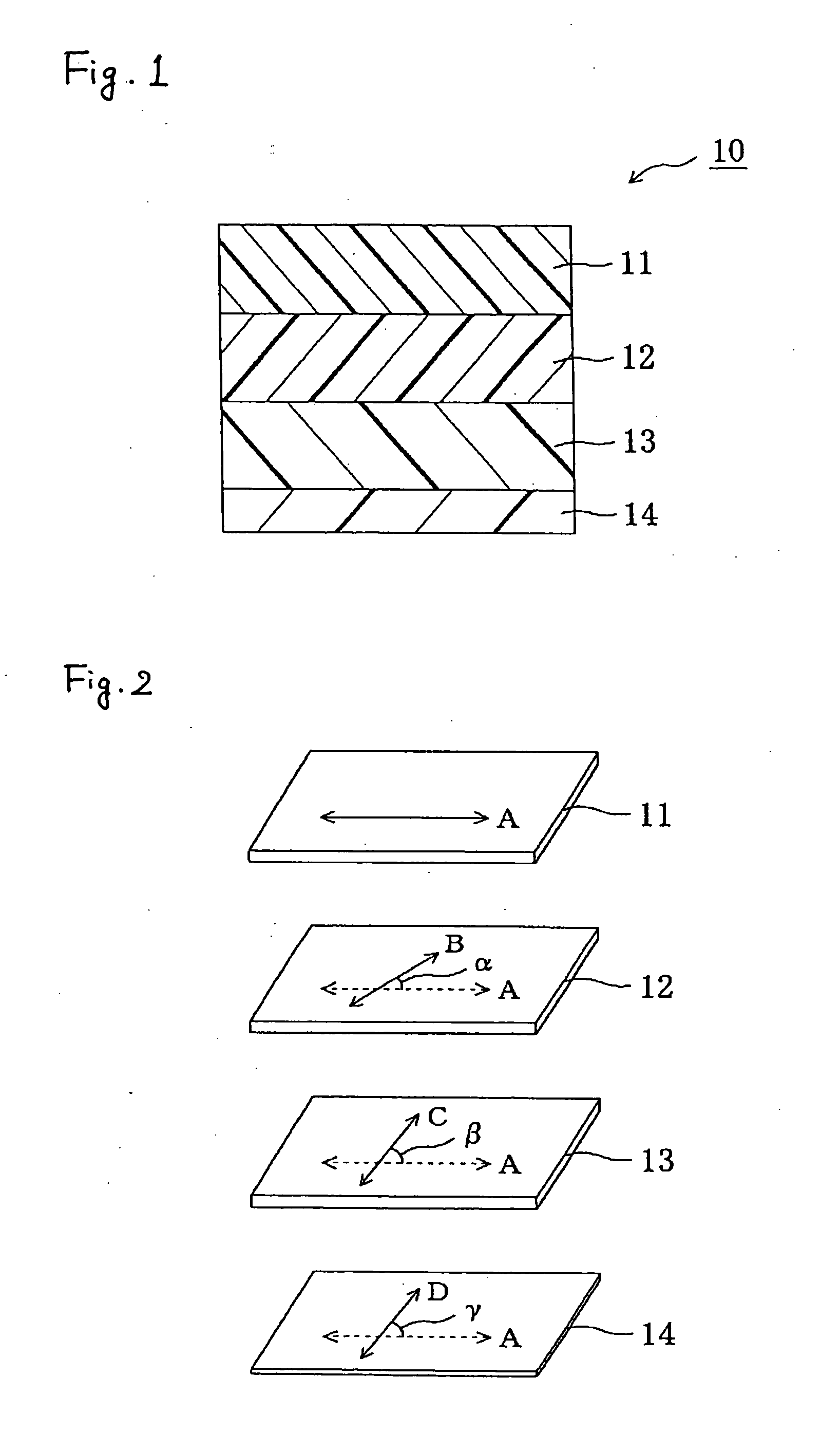
(Production of Polarizer)

[0132] A commercially available polyvinyl alcohol (PVA) film (available from Kuraray Co., Ltd.) was colored in an aqueous solution containing iodine and uniaxially stretched to about a 6 times length between rolls having different speed ratios in an aqueous solution containing boric acid, to thereby obtain a continuous polarizer. A commercially available TAC film (available from Fuji Photo Film Co., Ltd.) was attached to each side of the polarizer by using a PVA-based adhesive, to thereby obtain a polarizing plate (protective film / polarizer / protective film) having a total thickness of 100 μm. This polarizing plate was punched out into length of 20 cm and width of 30 cm such that an absorption axis of the polarizer was set in a longitudinal direction.

(Production of First Optical Compensation Layer)

[0133] A continuous norbornene-based resin film (trade name, Zeonoa, available from Zeon Corporation, thickness of 60 μm, photoelastic coefficient of 3.10×10⁻¹...

example 2

[0138] The polarizing plate, the first optical compensation layer, and the second optical compensation layer were produced in the same manner as in Example 1.

(Production of Third Optical Compensation Layer)

[0139] A continuous norbornene-based film (trade name, Arton, available from JSR Corporation, thickness of 100 μm, photoelastic coefficient of 5.00×10⁻¹² m2 / N) was longitudinally stretched to an about 1.27 times length at 175° C. and then transversely stretched to an about 1.37 times length at 176° C., to thereby produce a continuous film (thickness of 65 μm) for a third optical compensation layer. This film was punched out into length of 20 cm and width of 30 cm, to thereby form a third optical compensation layer. The third optical compensation layer had an in-plane retardation Re3 of 0 nm and a thickness direction retardation Rth3 of 110 nm.

(Production of Polarizing Plate Provided With Optical Compensation Layers)

[0140] A polarizing plate provided with optical compensation...

example 3

[0141] The polarizing plate, the first optical compensation layer, and the second optical compensation layer were produced in the same manner as in Example 1.

[0142] The liquid crystal application liquid prepared in the same manner as in Example 1 was used to coat a substrate (biaxially stretched PET film), subjected to heat treatment at 80° C. for 3 minutes, and subjected to polymerization treatment by irradiating the liquid crystal application liquid with UV light, to thereby form a cholesteric alignment fixed layer (thickness of 2 μm). Next, an isocyanate-based curable adhesive (thickness of 5 μm) was applied to the cholesteric alignment fixed layer, and a plastic film layer (TAC film, thickness of 40 μm) was attached thereto through the adhesive, to thereby form a third optical compensation layer. The third optical compensation layer was punched out into length of 20 cm and width of 30 cm. The third optical compensation layer had a thickness of 47 μm, an in-plane retardation Re3...


PUM

PropertyMeasurementUnit
thickness direction retardation Rth3aaaaaaaaaa
thicknessaaaaaaaaaa

Abstract

To provide a polarizing plate provided with optical compensation layers capable of contributing to thickness reduction, preventing uneven display due to heat, and favorably preventing light leak in black display, and an image display apparatus using the same. The polarizing plate provided with optical compensation layers of the present invention includes a polarizer, a first optical compensation layer, a second optical compensation layer, and a third optical compensation layer in the stated order. The first optical compensation layer, the second optical compensation layer, and the third optical compensation layer each have predetermined absolute value of photoelastic coefficient, refractive index profile, and in-plane retardation and/or thickness direction retardation. An absorption axis of the polarizer and a slow axis of the first optical compensation layer form an angle of 10° to 30°. The absorption axis of the polarizer and a slow axis of the second optical compensation layer form an angle of 70° to 95°. The absorption axis of the polarizer and a slow axis of the third optical compensation layer form an angle of 70°to 95°.

Description

TECHNICAL FIELD [0001] The present invention relates to a polarizing plate provided with optical compensation layers, and to an image display apparatus using the same. In particular, the present invention relates to a polarizing plate provided with optical compensation layers capable of contributing to thickness reduction, preventing uneven display due to heat, and favorably preventing light leak in black display, and to an image display apparatus using the same. BACKGROUND ART [0002] There is proposed a semi-transmissive reflective liquid crystal display apparatus as a liquid crystal display apparatus of VA mode, in addition to a transmissive liquid crystal display apparatus and a reflective liquid crystal display apparatus (see JP 11-242226 A and JP 2001-209065 A, for example). The semi-transmissive reflective liquid crystal display apparatus utilizes outside light in the same manner as in the reflective liquid crystal display apparatus in a bright place, and allows visualization ...

Claims


Application Information

Patent Timeline
Patent Type & Authority Applications(United States)
IPC IPC(8): G02F1/1335
CPCG02B5/3025G02F1/133528G02F1/13363G02F2001/133633G02F2413/11G02F2413/04G02F2413/07G02F2413/08G02F2202/40G02F1/133634G02F1/133633G02B5/30G02F1/1335
Inventor CHIBA, TSUYOSHIOKADA, HIROYUKIKITAMURA, YOSHITSUGUSHUTOU, SHUNSUKE
Owner NITTO DENKO CORP
Why Eureka
Try Eureka