Composite heatsink plate assembly

a heatsink plate and composite technology, applied in the direction of electrical apparatus construction details, light and heating apparatus, laminated elements, etc., can solve the problems of increasing fabrication costs, reducing the size of the machine, and reducing the size of the extruder, so as to reduce the cost of fabrication and reduce the size. , the effect of easy and rapid production

Inactive Publication Date: 2007-09-27
KUO MING SHO +1
View PDF13 Cites 13 Cited by
  • Summary
  • Abstract
  • Description
  • Claims
  • Application Information

AI Technical Summary

Benefits of technology

[0008] Another objective of the present invention is to provide a heatsink plate assembly, wherein the heatsink plates are laminated to have a determined width required by the heatsink plate assembly, so that the width of the heatsink plate assembly is increased according to the user's requirement without being limited to the width of the extruding machine, thereby facilitating fabrication of the heatsink plate assembly.
[0009] A further objective of the present invention is to provide a heatsink plate assembly, wherein each of the heatsink plates is made at a time without needing multiple working procedures, so that each of the heatsink plates is produced easily and rapidly, thereby decreasing costs of fabrication.
[0010] A further objective of the present invention is to provide a heatsink plate assembly, wherein each of the heatsink plates has a smaller size, so that each of the heatsink plates is made by the extruding machine easily and rapidly, to prevent the extruding machine from being worn out or inoperative due to an excessive size, thereby enhancing the working efficiency and the lifetime of the extruding machine.
[0011] A further objective of the present invention is to provide a heatsink plate assembly, wherein the width of the heatsink plate assembly can be adjusted arbitrarily according to the user's requirement, thereby enhancing the versatility of the heatsink plate assembly.

Problems solved by technology

However, the extruding machine having a larger size has a higher price, thereby increasing costs of fabrication.
In addition, the width and height of the extruding machine is limited.
However, production of the heatsink plate 2 needs more working procedures, thereby greatly increasing costs of fabrication.

Method used


Image

  • Composite heatsink plate assembly
  • Composite heatsink plate assembly
  • Composite heatsink plate assembly

Examples


Embodiment Construction

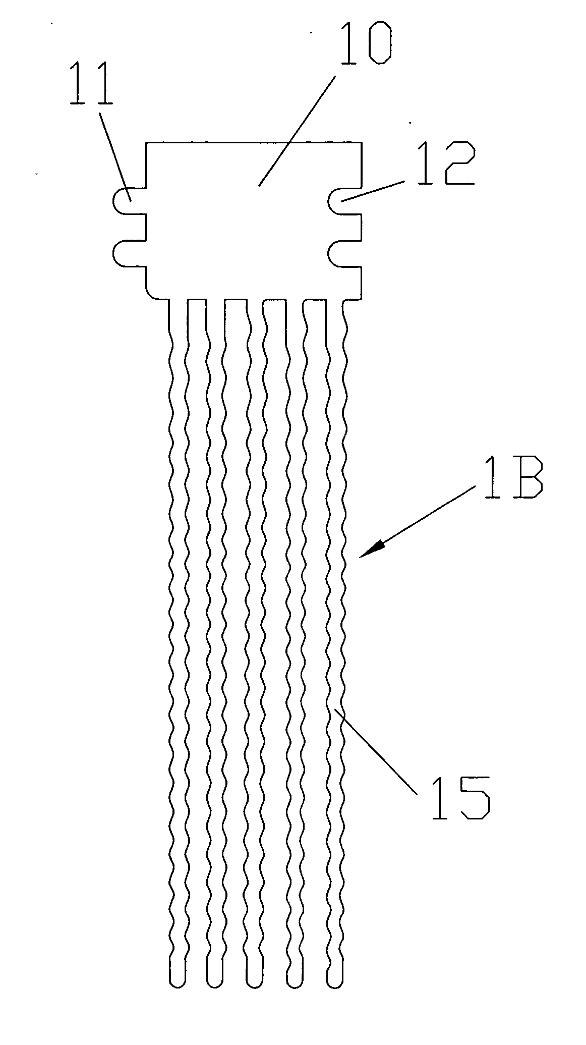
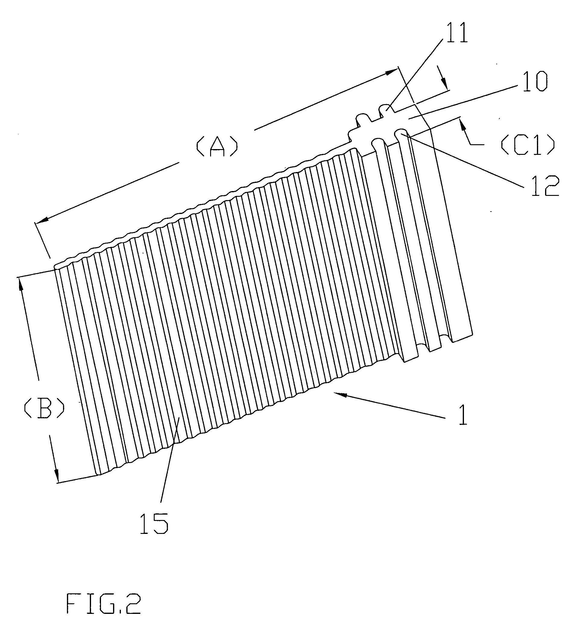
[0023] Referring to the drawings and initially to FIGS. 1-3, a composite heatsink plate assembly in accordance with the preferred embodiment of the present invention comprises a plurality of heatsink plates 1 laminating each other as shown in FIG. 3.

[0024] Each of the heatsink plates 1 is integrally formed by an extruding process. Each of the heatsink plates 1 has a length (A) equal to that of the heatsink plate assembly and has a height (B) equal to that of the heatsink plate assembly. Each of the heatsink plates 1 has a width (C1), and the heatsink plates 1 are laminated to have a width (C) equal to that of the heatsink plate assembly as shown in FIG. 3.

[0025] Each of the heatsink plates 1 has a first side formed with at least one locking tenon 11 and a second side opposite to the first side and formed with at least one locking mortise 12. In the preferred embodiment of the present invention, each of the heatsink plates 1 has a plurality of locking tenons 11 and a plurality of l...


PUM


Abstract

A heatsink plate assembly includes a plurality of heatsink plates laminating each other. Each of the heatsink plates has a first side formed with at least one locking tenon and a second side formed with at least one locking mortise. Thus, the heatsink plates are laminated to have a determined width required by the heatsink plate assembly, so that the width of the heatsink plate assembly is increased according to the user's requirement without being limited to the width of the extruding machine, thereby facilitating fabrication of the heatsink plate assembly. In addition, each of the heatsink plates is made at a time without needing multiple working procedures, so that each of the heatsink plates is produced easily and rapidly, thereby decreasing costs of fabrication.

Description

BACKGROUND OF THE INVENTION [0001] 1. Field of the Invention [0002] The present invention relates to a heatsink plate assembly and, more particularly, to a composite heatsink plate assembly. [0003] 2. Description of the Related Art [0004] A conventional heatsink plate 2 in accordance with the prior art shown in FIG. 10 is integrally formed by an extruding process. In general, the heatsink plate 2 is formed by an extruding machine having a larger size. However, the extruding machine having a larger size has a higher price, thereby increasing costs of fabrication. In addition, the width and height of the extruding machine is limited. [0005] Alternatively, a plurality of smaller plates are formed by an extruding machine having a smaller size, and the smaller plates are packed by a hydraulic machine or by a punching press to form the heatsink plate 2. However, production of the heatsink plate 2 needs more working procedures, thereby greatly increasing costs of fabrication. BRIEF SUMMARY...

Claims


Application Information

Patent Timeline
Patent Type & Authority Applications(United States)
IPC IPC(8): H05K7/20
CPCF28F3/02H01L21/4882H01L23/367H01L2924/0002H01L2924/00
Inventor KUO, MING-SHOKUO, ERH-WEN
Owner KUO MING SHO
Why Eureka
Try Eureka