
Subterranean chamber encapsulation system

a technology of subterranean chambers and encapsulation systems, which is applied in the direction of soil conditioning compositions, other domestic articles, synthetic resin layered products, etc., can solve the problems of energy efficiency loss

Inactive Publication Date: 2007-09-27
JANESKY LAWRENCE M
View PDF2 Cites 16 Cited by
  • Summary
  • Abstract
  • Description
  • Claims
  • Application Information

AI Technical Summary

Benefits of technology

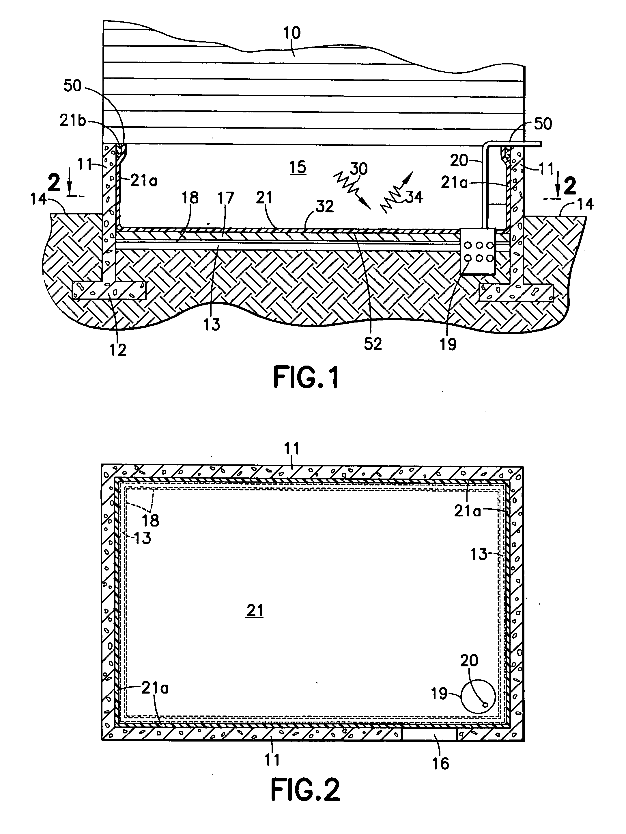
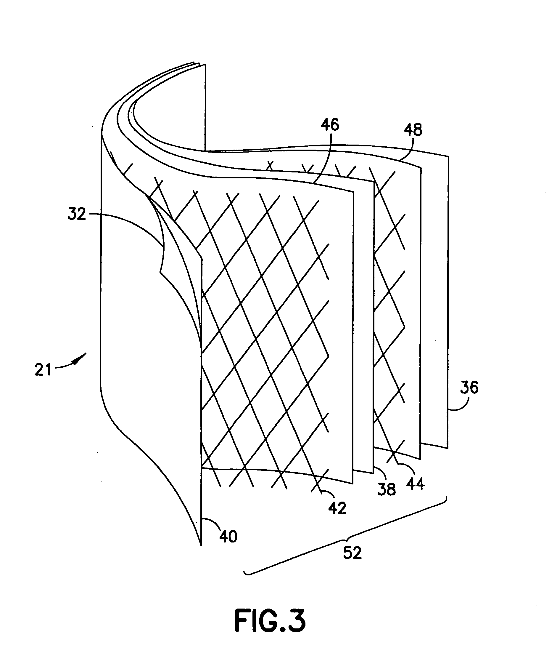
[0006] In accordance with another exemplary embodiment, a partially subterranean chamber sealing system for sealing at least a partially subterranean chamber of a building is provided. The system comprises a flexible liner having first and second high density layers. A reinforcing layer is disposed between the first and the second high density layers. A bonding layer is disposed between the first and the second high density layers. A reflective layer is adhered to either the first or second high density layers. The flexible liner is durable to repeatedly support a user walking or crawling thereon without tearing or breaking through the flexible liner. The bonding layer bonds the first and second high density layers together with the reinforcing layer disposed there between. The high density layers are adapted to prevent air or water vapor from passing there through. The reflective layer is adapted to reflect heat radiated thereon.
[0007] In accordance with another exemplary embodiment, a partially subterranean chamber sealing system for sealing at least a partially subterranean chamber of a building is provided. The system comprises a seal barrier disposed on at least a portion of the chamber for forming a sealed chamber with the seal barrier being flexible and conformal in shape so as to substantially conform to an uneven floor or wall of the chamber. A seal is disposed between at least a portion of the seal barrier and at least a portion of the chamber. The seal is adapted to seal the seal barrier to the chamber. The seal barrier comprises a sealing layer. A radiant barrier is connected to the seal barrier. The seal is adapted to prevent air or water vapor from passing there by. The seal barrier is adapted to prevent air, water or vapor from passing there through. The radiant barrier is adapted to reflect a substantial portion of radiated heat.

Problems solved by technology

Basements or crawlspaces may allow moisture and water vapor, for example, from dirt or concrete floors, to enter the building structure located above the space causing multiple problems, such as insect infestation or structural problems.
A problem arises when there is a temperature difference, for example between the building's crawlspace and the outdoors, where energy efficiency is lost.

Method used


Image

  • Subterranean chamber encapsulation system
  • Subterranean chamber encapsulation system
  • Subterranean chamber encapsulation system

Examples


Embodiment Construction

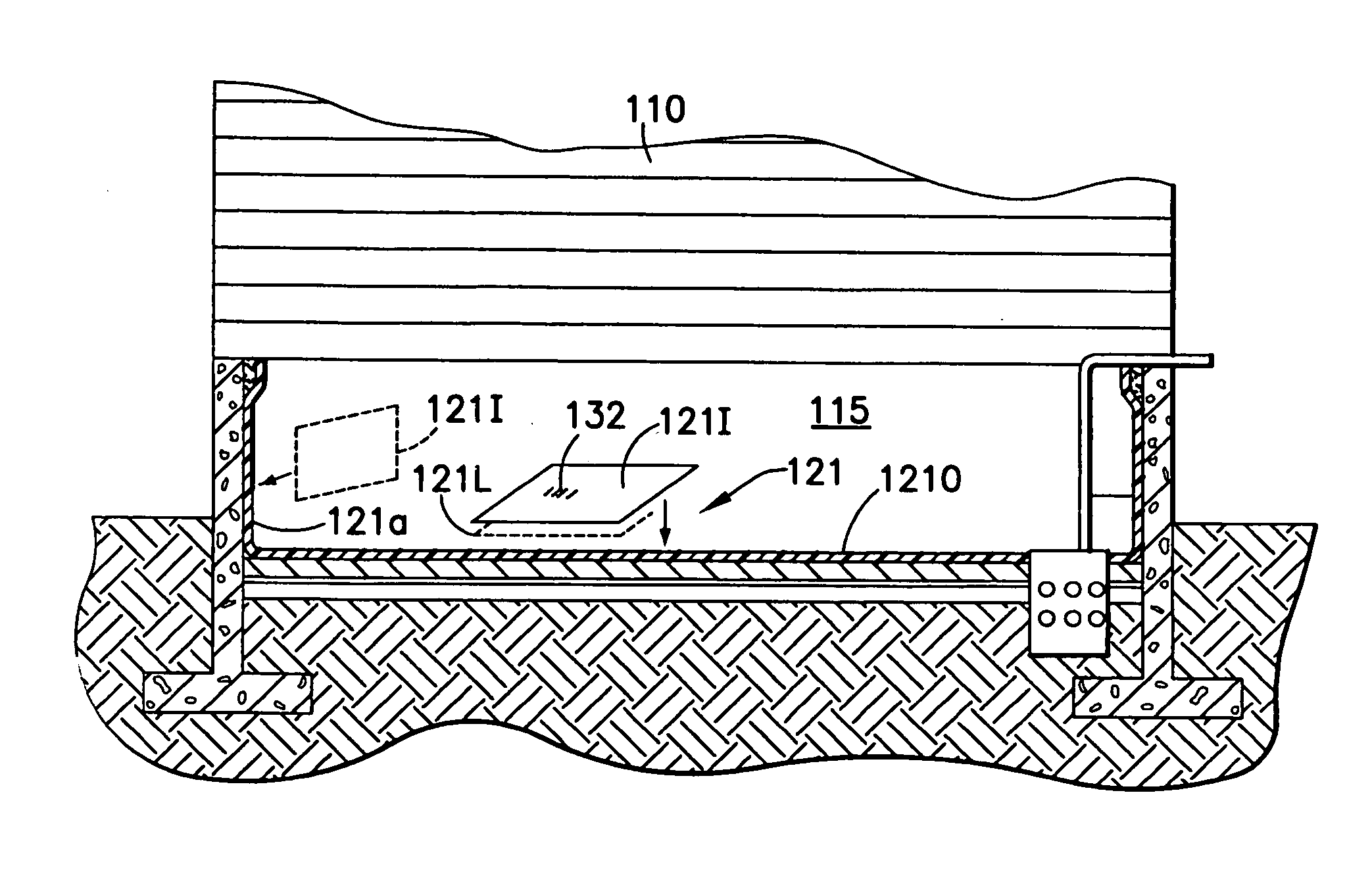
[0005] In accordance with one exemplary embodiment, a partially subterranean chamber sealing system for sealing at least a partially subterranean chamber of a building is provided. The system comprises a flexible liner disposed on at least a portion of a surface bounding the chamber for forming a seal boundary of the chamber. The liner has a peripheral edge sealed to the surface lined by the liner for insulating the surface from the chamber. The flexible liner comprises a sealing layer and a radiant barrier disposed on the sealing layer.

[0006] In accordance with another exemplary embodiment, a partially subterranean chamber sealing system for sealing at least a partially subterranean chamber of a building is provided. The system comprises a flexible liner having first and second high density layers. A reinforcing layer is disposed between the first and the second high density layers. A bonding layer is disposed between the first and the second high density layers. A reflective laye...


PUM

PropertyMeasurementUnit
Densityaaaaaaaaaa
Flexibilityaaaaaaaaaa
aaaaaaaaaa

Abstract

A partially subterranean chamber sealing system for sealing at least a partially subterranean chamber of a building is provided. The system comprises a flexible liner disposed on at least a portion of a surface bounding the chamber for forming a seal boundary of the chamber. The liner has a peripheral edge sealed to the surface lined by the liner for insulating the surface from the chamber. The flexible liner comprises a sealing layer and a radiant barrier disposed on the sealing layer.

Description

BACKGROUND [0001] 1. Field [0002] The exemplary embodiments disclosed herein relate to a subterranean chamber encapsulation system and, more particularly, to a subterranean chamber encapsulation system with a radiant barrier. [0003] 2. Brief Description of Related Developments [0004] Basements or crawlspaces may allow moisture and water vapor, for example, from dirt or concrete floors, to enter the building structure located above the space causing multiple problems, such as insect infestation or structural problems. A solution exists to provide a lining over the inside of the crawl space where the lining provides a vapor barrier between the dirt floor or vapor source and the structure to isolate the structure from the high humidity environment. One such system is disclosed in U.S. Pat. No. 6,575,666 which is incorporated by reference herein in its entirety. A problem arises when there is a temperature difference, for example between the building's crawlspace and the outdoors, where...

Claims


Application Information

Patent Timeline
IPC IPC(8): B32B15/08E02D19/00
CPCB32B27/12B32B2581/00E02D31/02E04B1/66E04B1/70B32B15/08B32B15/20B32B27/065B32B27/08B32B27/32B32B27/36B32B2255/10B32B2255/205B32B2262/101B32B2266/08B32B2307/304B32B2307/7246B32B2419/00E02D31/008E04B1/665
Inventor JANESKY, LAWRENCE M.
Owner JANESKY LAWRENCE M
Learn More