Control system for a transformer or reactor

a control system and transformer technology, applied in the direction of error detection/correction, special data processing applications, digital computer details, etc., can solve the problems of high cost, inability to achieve the desired signal format, and inability to fully replace the control system and cabinet of the existing system, so as to prevent the carbonization of the tap-changer and substantially increase the possibility of contact carbonization.

Active Publication Date: 2007-09-27
HITACHI ENERGY SWITZERLAND AG
View PDF13 Cites 20 Cited by
  • Summary
  • Abstract
  • Description
  • Claims
  • Application Information

AI Technical Summary

Benefits of technology

[0012]An integrated electronic control and monitoring system according to a first advantageous embodiment of the invention, may comprise an electronic board rack including, a main processor board and various peripheral boards. It is contemplated that the boards may be configured to handle both analog and digital input / output signals of various types and formats so that these may be directly coupled to the electronic control system. This provides the advantage that it is possible to combine and exchange boards of all types in the rack. Further each signal may be configured individually at any channel on each board.
[0015]The networked system, further allows for support for sensors that communicates via CAN (Control Area Network) bus, e.g. Hydran, where the CAN sensors may be configured directly in the electronic control system. When voltage measurement is connected to the transformer electronic control system, it is possible to regulate voltage with LTC via bus communication.
[0019]It is advantageous to use the second calculated temperature to compensate for multiple operations of the tap-changer, which may generate additional heating. If however, the temperature increase in the tap-changer exceeds preset increase values, the system may alarm at a first lower threshold level, and may further trip at a second higher threshold level.
[0020]Further, a system and method are provided that may be integrated with existing equipment, for monitoring transformer / reactor operation and tap-changer operation to substantially prevent tap-changer carbonization. For example, if a tap-changer is placed on one contact for an extended period of time, the possibility of contact carbonization substantially increases. Once carbonization begins, the contacts are being damaged, therefore, one object for the diagnostic method is to substantially avoid carbonization.

Problems solved by technology

Historically, control systems did not provide for the sophisticated levels of control and monitoring that are highly desirable by means of network connections.
There are relatively large numbers of control cabinets and installations where the control system, while electronic in nature, is not compatible with current networking and communications technology.
However, a problem involved with this conversion is that the costs involved with removing the control system and cabinet of the existing system and fully replacing it with an updated electronic system are correspondingly high, both in terms of materials and labor.
To replace the equipment so that a desired signal format can be generated is impractical and extremely costly.
In relatively large commercial applications, the heat build up that may occur in a tap-changer due to, for example, incomplete switch over or change of a tap setting, can quickly lead to a catastrophic failure of the transformer.
This could present a danger to individuals as well as be quite costly both in terms of replacement cost for the transformer and associated equipment, and downtime for customers.
However, the monitoring systems of many current tap-changers do not lend themselves well to being integrated with a networked control system.
The numerous formats of the control and monitoring signals in existing installations further compound the challenge.
Still another challenge facing tap-changing systems is that, even during normal use of the transformer, the various contacts in the tap-changer will wear over time as current is switched by the tap-changer.
This is highly disadvantageous because carbon deposits tend to insulate or increase the resistance to the flow of current.
If ignored, overheating and arcing due to the poor contact can lead to catastrophic failure of the device may occur.

Method used


Image

  • Control system for a transformer or reactor
  • Control system for a transformer or reactor
  • Control system for a transformer or reactor

Examples


Embodiment Construction

[0040]Referring now to the drawings, wherein like reference numerals designate corresponding structure throughout the views.

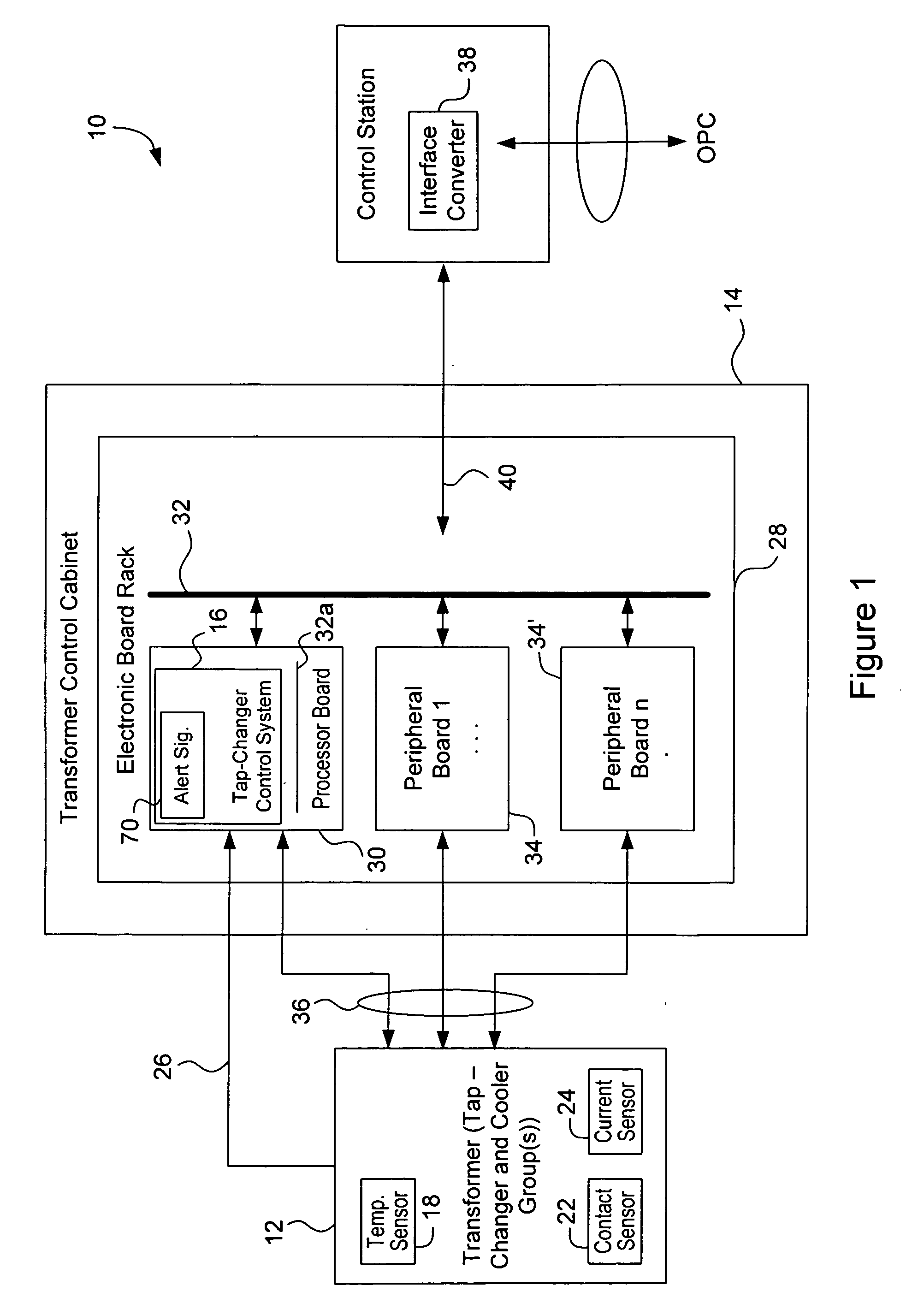
[0041]FIG. 1 illustrates one advantageous embodiment of universal control system 10 and generally comprises transformer (tap-changer and cooling group(s)) 12, transformer cabinet 14 and tap-changer control system 16.

[0042]Transformer (tap-changer and cooling group(s)) 12 is, in one advantageous embodiment, provided with temperature sensors 18, which are provided to sense the temperature in the vicinity of the tap-changer and transformer top oil and transformer bottom oil temperatures. Temperature sensors 18 may comprise virtually any type of commercially-available temperature sensors.

[0043]Transformer (tap-changer and cooling group(s)) 12 may also be variously provided with contact sensor 22 for measuring the total time a contact (not shown) has been closed, and with a current sensor 24 to measure the amount of current passing through the contact.

[0044]In one e...


PUM


Abstract

A universal control and diagnostic system for a transformer that may be retrofit with existing control and tap-changer equipment, the system providing for remote monitoring and control of the equipment and for measuring various criteria associated with the tap-changer to substantially minimize damage to the equipment during a maneuver and for substantially avoiding carbonization of a connected contact.

Description

FIELD OF THE INVENTION[0001]The present invention relates generally to a control system for a transformer or reactor and means for carrying out diagnostics of a tap-changer and methods for carrying out such diagnostics.BACKGROUND OF THE INVENTION[0002]Control systems for monitoring and changing of tap settings on transformers have been utilized with varying levels of success and efficiency. Historically, control systems did not provide for the sophisticated levels of control and monitoring that are highly desirable by means of network connections.[0003]There are relatively large numbers of control cabinets and installations where the control system, while electronic in nature, is not compatible with current networking and communications technology. It is desirable to convert many of the existing control system over to a format that may easily be controlled and monitored remotely over, for example, a network. However, a problem involved with this conversion is that the costs involved...

Claims


Application Information

Patent Timeline
Patent Type & Authority Applications(United States)
IPC IPC(8): G06F19/00G06F17/40
CPCG01R31/027G01R31/3274H02H7/055H01H2009/0061H01F29/04G01R31/62H01H9/00G01R31/327
Inventor STENESTAM, BENGT-OLOFANDERSSON, GUNNAR
Owner HITACHI ENERGY SWITZERLAND AG
Why Eureka
Try Eureka