Binary code instrumentation to reduce effective memory latency

a technology of effective memory latency and binary code, applied in the field of computer systems, can solve the problems of many processor cycles wasted, relative improvements in application performance, and change in processor clock rate, so as to prevent processor stalls and reduce effective memory latency

Active Publication Date: 2007-09-27
ORACLE INT CORP
View PDF11 Cites 21 Cited by
  • Summary
  • Abstract
  • Description
  • Claims
  • Application Information

AI Technical Summary

Benefits of technology

[0012] In one embodiment, the code analyzer may be further configured to select, as the instruction stream, a portion of the compiled executable version of an application program to be optimized for performance. For example, the code analyzer may, in conjunction with or as part of a Just In Time (JIT) compiler at a Java™ virtual machine (JVM), select a frequently executed code portion of an application for optimization. The code analyzer may be configured to dynamically insert instrumentation code into the selected instruction stream to identify potential prefetch opportunities. During a subsequent run of the instrumented code, the code analyzer may gather instrumentation data output by the instrumentation code, and use the instrumentation data to inser...

Problems solved by technology

However, changes in processor clock rates do not always result in similar relative improvements in application performance as perceived by end users.
If processors frequently have to wait for data or instructions to be received from memory, many processor cycles may be wasted instead of being used for doing “useful” work, thus reducing the impact of faster clock rates on application performance.
However, cache implementations usually involve tradeoffs between cache size and proximity to the processors; it may not always be feasible to implement large enough caches sufficiently close (in terms of access latency) to the processors to overcome the memory latency problems.
While accesses to L1 caches may be fast (e.g., a few ...

Method used


Image

  • Binary code instrumentation to reduce effective memory latency
  • Binary code instrumentation to reduce effective memory latency
  • Binary code instrumentation to reduce effective memory latency

Examples


Embodiment Construction

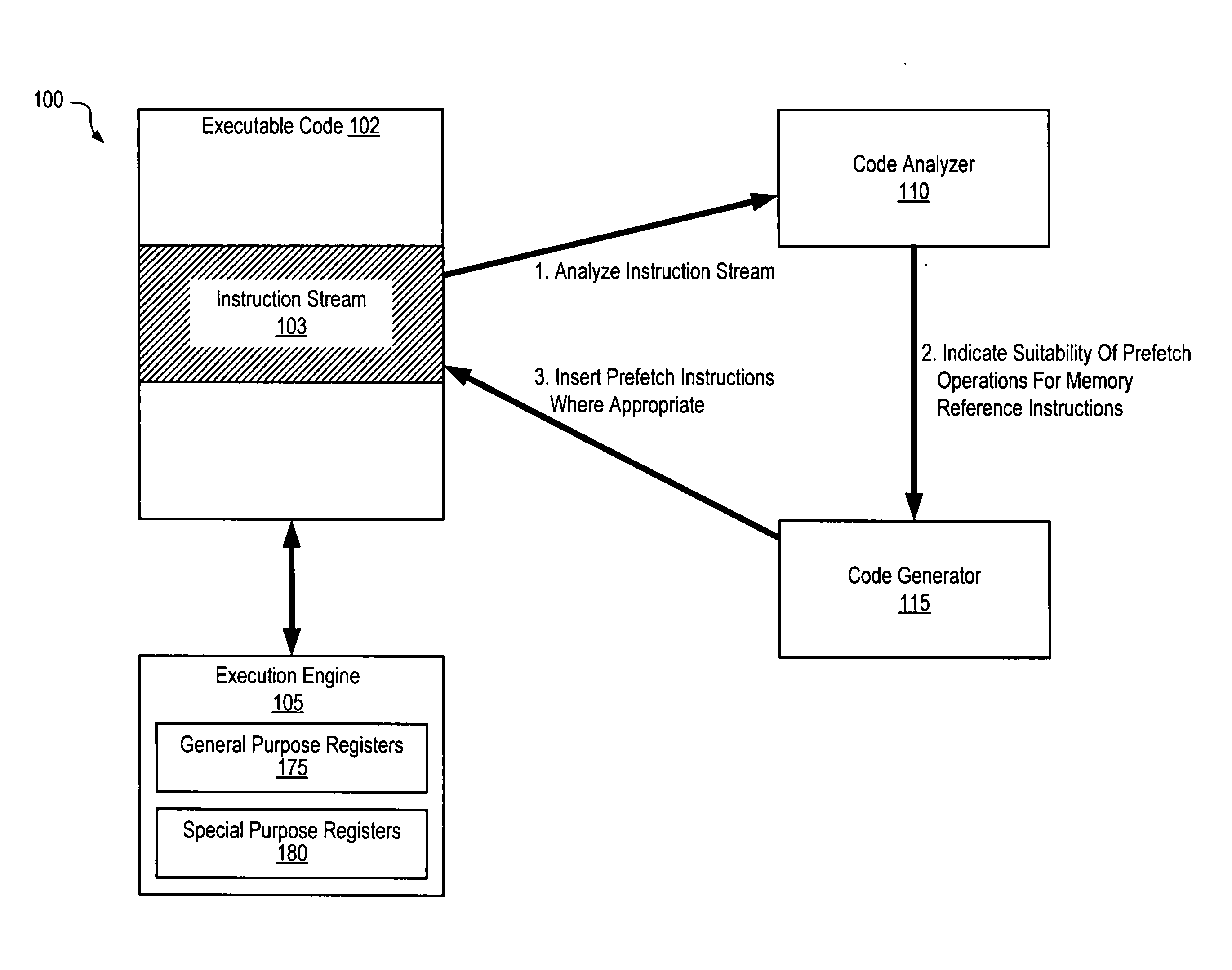
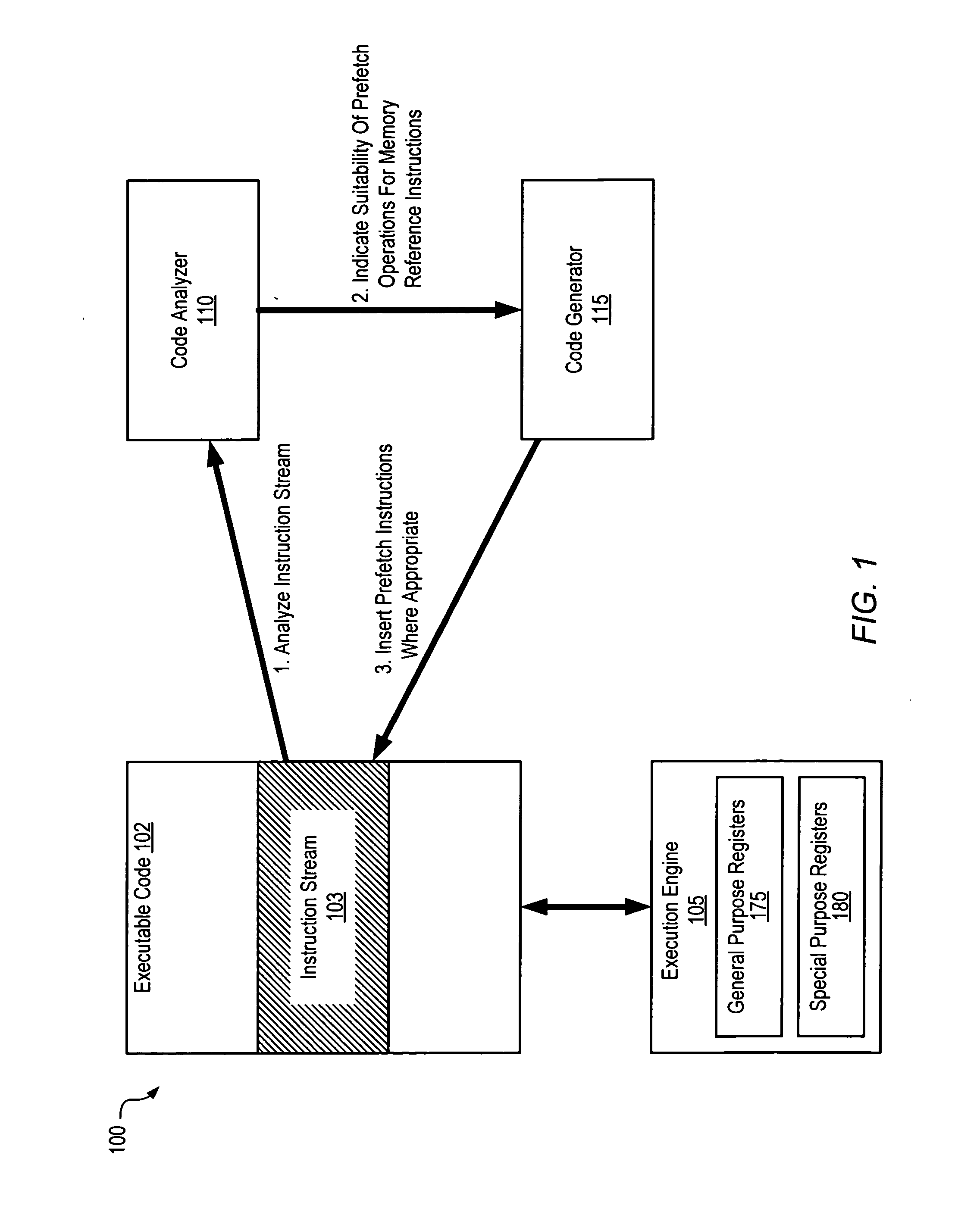
[0022]FIG. 1 is a block diagram illustrating one embodiment of a system 100. The system includes an execution engine 105, compiled executable code 102 targeted for execution at the execution engine, a code analyzer 110 and a code generator 115. In various embodiments, the execution engine 105 may comprise a hardware processor, a simulator of a processor or computer system, or an emulator of a processor or system. The executable code 102 may comprise the instructions for one or more applications and / or the instructions for infrastructure software such as an operating system, an application server or other middleware, etc. The code analyzer 110 may be configured to analyze at least a subset of the executable code 102 (as indicated by the arrow labeled “1” in FIG. 1), which may be termed an instruction stream 103 herein, for potential opportunities for prefetch operations, as described below in further detail. In one embodiment, for example, the execution engine may include a set of re...


PUM


Abstract

A system for binary code instrumentation to reduce effective memory latency comprises a processor and memory coupled to the processor. The memory comprises program instructions executable by the processor to implement . a code analyzer configured to analyze an instruction stream of compiled code executable at an execution engine to identify, for a given memory reference instruction in the stream that references data at a memory address calculated during an execution of the instruction stream, an earliest point in time during the execution at which sufficient data is available at the execution engine to calculate the memory address. The code analyzer generates an indication of whether the given memory reference instruction is suitable for a prefetch operation based on a difference in time between the earliest point in time and a time at which the given memory reference instruction is executed during the execution.

Description

[0001] The U.S. Government has a paid-up license in this invention and the right in limited circumstances to require the patent owner to license others on reasonable terms as provided for by the terms of Contract No. NBCH3039002 awarded by the Defense Advanced Research Projects Agency (DARPA).BACKGROUND OF THE INVENTION [0002] 1. Field of the Invention [0003] The present invention is directed to computer systems. More particularly, it is directed to techniques to reduce latency of memory access operations within instruction streams executed at computer processors. [0004] 2. Description of the Related Art [0005] Microprocessor speeds have been increasing dramatically as the underlying semiconductor technology has advanced. Central processing units used in single-user workstations and even in laptops today are often, at least in terms of clock rates, several times faster than the fastest processors in use just a few years ago. However, changes in processor clock rates do not always re...

Claims


Application Information

Patent Timeline
IPC IPC(8): G06F9/44
CPCG06F12/0862G06F2212/6028G06F2212/601
Inventor SHARAPOV, LLYA A.OVER, ANDREW J.
Owner ORACLE INT CORP
Why Eureka
Try Eureka