Product and Method of Forming a Gradient Density Fibrous Filter

a fibrous filter and gradient density technology, applied in the field of filters, can solve the problems of many prior designs that fail to provide uniform loading and desired efficiency, and achieve the effect of improving filtration performance and improving particulate filtration efficiency

Inactive Publication Date: 2007-10-04
AAF MCQUAY INC
View PDF27 Cites 69 Cited by
  • Summary
  • Abstract
  • Description
  • Claims
  • Application Information

AI Technical Summary

Benefits of technology

[0011] More particularly, the present invention provides a multi-thickness filter media comprising a combination of at least two successive adjacent intertangled thicknesses of chopped fibers wherein each thickness has substantially different combined denier fibers than other thicknesses. The average pore size characteristics of one thickness differs from that of an adjacent thickness with the different combination of fiber sizes of one thickness being comparatively finer, on the average, than the fibers of the other thickness forming different combinations of fiber and pore sizes of the successive intertangled thicknesses in order to improve filtration performance. In a preferred embodiment, the intertangled thicknesses form substantially a single thickness having an overall gradient density and stiffness sufficient to be self supporting. Further, the present invention provides a unified method of manufacturing such filter media comprising: collecting a first thickness of chopped fibers in a hopper-collector zone, the first thickness of chopped fibers being of a first combination of fibers and pore sizes; collecting at least a second thickness of chopped fibers in a hopper collector zone to be successively joined in overlying intertangled relation with the first thickness of chopped fibers, the second thickness of chopped fibers being of a second combination of fibers and pore sizes different from the fibers and pore sizes of the first thickness of chopped fibers with the combination of fibers of one thickness being finer than that of fibers of the other thickness; passing the first and second thicknesses to a carding zone, individually or together, to open and align the chopped fibers in each thickness, calendaring at least one side of the combined thicknesses, the successively joined filter thicknesses having an intertangled relationship to improve particulate filtration efficiency and extended life of filter with the overall average pore size and permeability of the combined successive intertangled thicknesses being substantially a single layer of filter media having a gradient density.

Problems solved by technology

Hence, improving life of filter and efficiency in a filtration media without substantially increasing the pressure drop across the filtration media remains a challenge in improving filtration performance.
However, in general, many of these prior designs fail to provide uniform loading and a desired efficiency.

Method used


Image

  • Product and Method of Forming a Gradient Density Fibrous Filter
  • Product and Method of Forming a Gradient Density Fibrous Filter
  • Product and Method of Forming a Gradient Density Fibrous Filter

Examples


Embodiment Construction

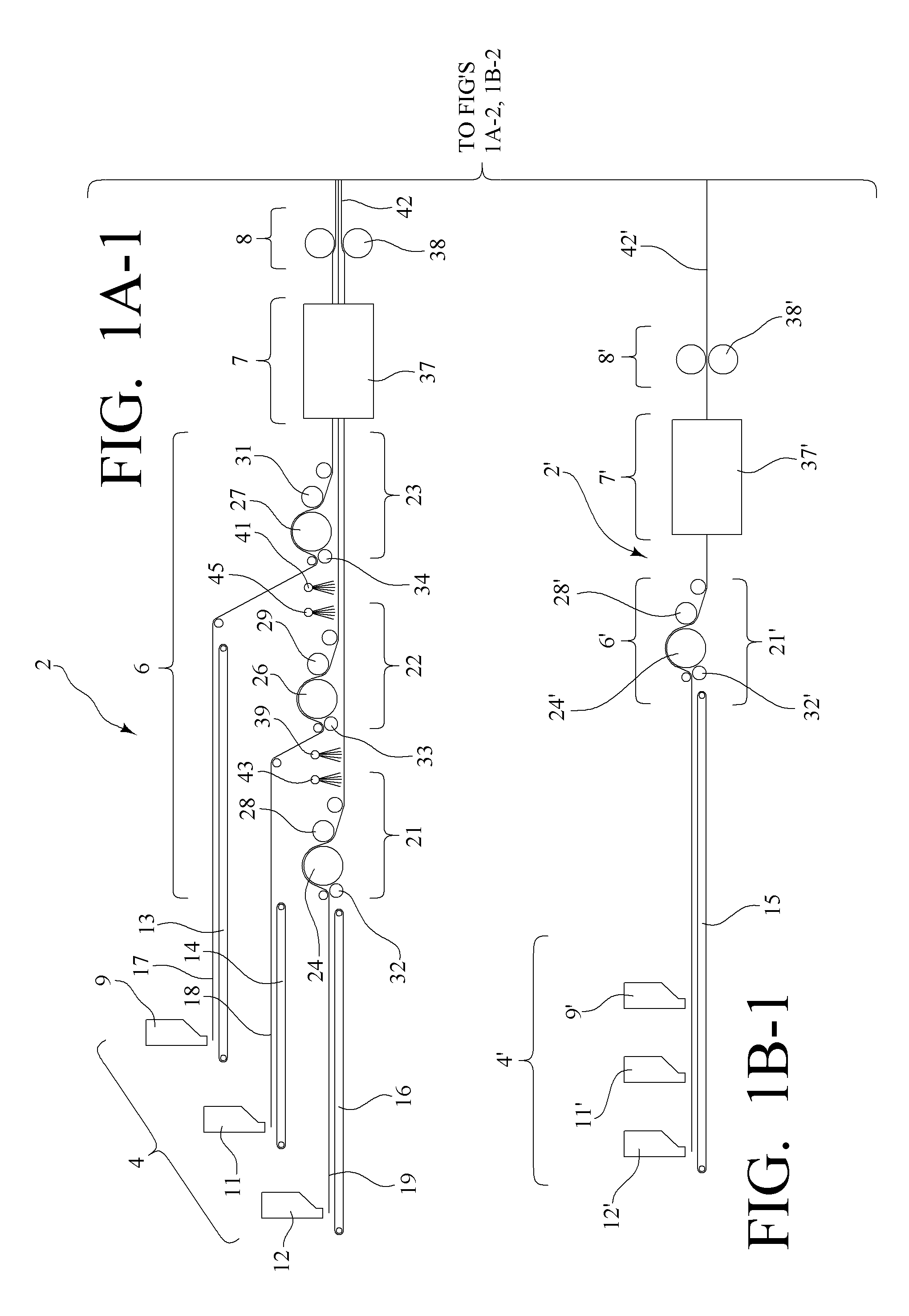
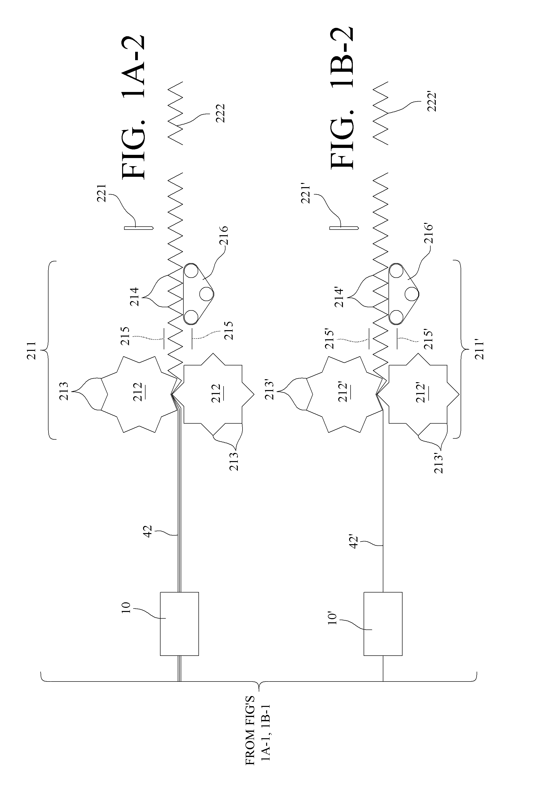
[0022] Referring specifically to FIG. 1A-1, 1B-1, 1A-2, and 1B-2 of the figures, schematic flow diagrams 2 and 2′ are disclosed, these diagrams each schematically include several sections arranged successively and substantially in-line to produce gradient density filter media 222 and 222′ such as disclosed in FIGS. 1A-2 and 1B-2 respectively of the figures. The disclosed flow-diagrams in FIGS. 1A-1 and 1B-1, each broadly include four process sections—namely, the bracketed mixer-blender sections 4 and 4′, the bracketed carding sections 6 and 6′, the bracketed heating sections 7 and 7′ and the bracketed calendering sections 8 and 8′. Mixer-blender section 4, as shown FIG. 1A-1, discloses three spaced mixer-blenders 9, 11 and 12. These mixer-blenders 9, 11 and 12 can be arranged with the outlets at different spaced levels to feed blended chopped fibers of size ranges to endless collector belts 13, 14, and 16, respectively, spaced at different levels to cooperate respectfully with the o...


PUM

PropertyMeasurementUnit
mean flow pore diameteraaaaaaaaaa
flow pore diameteraaaaaaaaaa

Abstract

A filter media product and method of making the same wherein at least two filter media thicknesses of differing average coarse and fine fiber sizes are held in intertangled relationship forming a gradient density fibrous filter media with the fiber sizes having an overall average in successive thicknesses being either greater or less than the average fiber size of the intertangled fiber thickness(es).

Description

CROSS-REFERENCE TO RELATED APPLICATIONS [0001] This patent application claims priority from and is a continuation-in-part of, currently pending, U.S. patent application Ser. No. 10 / 882,856, filed Jul. 1, 2004, hereby incorporated herein by reference, which claims priority as a divisional patent application from U.S. patent application Ser. No. 09 / 781,786, filed on Feb. 12, 2001, abandoned. This current patent application also claims priority from and is a continuation-in-part patent application of, currently pending, U.S. patent application Ser. No. 11 / 006,429, filed Dec. 7, 2004, hereby incorporated herein by reference, which claims priority as a divisional patent application from U.S. patent application Ser. No. 09 / 781,786, filed on Feb. 12, 2001, abandoned.SPONSORED RESEARCH OR DEVELOPMENT [0002] Not applicable. FIELD OF INVENTION [0003] The present invention relates to filters, such as gas or air filters, and methods of forming filters. BACKGROUND OF THE INVENTION [0004] The pre...

Claims


Application Information

Patent Timeline
Patent Type & Authority Applications(United States)
IPC IPC(8): B01D39/00B01D53/22B29B9/10
CPCB01D39/163B01D2239/0208B01D2239/0216B01D2239/10B01D2239/0435B01D2239/045B01D2239/0668B01D2239/0407Y10S55/44Y10S55/05Y10S55/39
Inventor CHOI, KYUNG-JU
Owner AAF MCQUAY INC
Why Eureka
Try Eureka