Steam Generator

a generator and steam technology, applied in the direction of steam generation using hot heat carriers, ignition automatic control, lighting and heating apparatus, etc., can solve the problems of high labor intensity, high labor intensity, and high labor intensity, and achieve the effect of reducing labor intensity, reducing labor intensity, and reducing labor intensity

Inactive Publication Date: 2007-10-04
ALSTOM TECH LTD
View PDF11 Cites 3 Cited by
  • Summary
  • Abstract
  • Description
  • Claims
  • Application Information

AI Technical Summary

Benefits of technology

[0009]One aspect of the present invention includes a steam generator with a pressure-tight pressure casing which encloses a volume and in which extends at least one hollow tube which is hermetically sealed in relation to the volume, which hollow tube is connected in each case to a feed and a discharge section which project through the pressure casing in a fluidtight manner, wherein at least one opening for feed of a heat flow into the volume, and also at least one opening for outlet of the heat flow, which engages in thermal interaction with the at least one hollow pipe, is provided in the pressure casing, in such a way that on one hand the production expenditure is to be significantly reduced compared with the steam generator principle which is explained at the beginning, so that the production costs can be reduced. Moreover, on the other hand it is necessary to create a constructional form of a steam generator which is as compact and low in construction as possible so that the steam generator can be placed as close as possible to a gas turbine plant, as far as possible beneath the operating platform. In this way, it can be possible to form the pipes, which are required for the exchange of heat flow between gas turbine plant and steam generator, as short as possible, in order to generate the lowest possible resulting pressure losses. Finally, it is possible to improve the efficiency of a whole combined power plant.
[0010]In another aspect of the present invention, a steam generator is formed by the pressure casing being formed in the shape of a drum, and has a longitudinal axis and also a diameter which measures perpendicularly to the longitudinal axis. Unlike the hitherto customary positioning of such well known drum-shaped pressure casings, the steam generator concept, according to this aspect, provides that the pressure casing is placed in a horizontal position so that the longitudinal axis of the pressure casing is oriented horizontally, or largely horizontally, and, consequently, the pressure casing has a longitudinal extent which is greater than its diameter. The horizontal arrangement of the pressure casing, according to this aspect, brings about in an advantageous way an appreciable reduction of the overall height of the steam generator, as a result of which new possibilities of the arrangement of the pressure casing relative to a gas turbine plant are opened up.
[0012]A special aspect of the steam generator which is formed according to the present invention provides a high as possible packing density of the hollow tube sections which are guided parallel to each other in each case, and which are allocated in each case to a plurality of individual hollow tubes, wherein the entirety of the individual vertical hollow tube stacks, which are arranged spatially as close as possible to each other, fill out volume sections of the pressure casing which are as large as possible. The heat flow inlet into the pressure casing is carried out for a heat transfer which is as effective as possible, on the part of the heat flow, to the hollow tubes and, ultimately, to the evaporable fluid which is guided inside the hollow tubes, in such a way that the heat flow passes once through the hollow tube arrangement transversely to the extent of the individual hollow tube sections, for which reason the steam generator concept according to the solution also corresponds to the OTC concept which was described at the beginning, i.e., the heat flow passes once through the hollow tube arrangement and transfers heat to the hollow tube arrangement during this once-through passage. In order to improve the thermal interaction between heat flow and hollow tube arrangement, at least one hollow tube is designed in an advantageous way with finned effect, i.e., is provided with a contoured tube surface form in order to increase the hollow tube surface on one hand, and on the other hand to improve the heat transfer between heat flow and hollow tube.
[0015]In addition to the low type of construction of the steam generator according to the present invention, which is advantageously achievable by the horizontal positioning of the drum-shaped pressure casing, the steam generator concept according to the solution, moreover, enables an appreciably simplified assembly, especially a simplified assembly of the hollow tube arrangement which can be produced in a far shorter assembly time and by managing with far fewer technically exacting assembly steps. The hollow tube arrangement, which is to be introduced inside the pressure casing, and which is preferably assembled from a plurality of individual tubes, can finally be assembled according to a simple mechanical assembly technique. If it is assumed, for example, that each individual hollow tube has a plurality of hollow tube sections which lie above each other in meander form and which are interconnected in a parallel guided manner and in their turn correspond to a vertical stack, and if it is further assumed that the hollow tube has a round tube cross section, then it is possible, by placing next to each other similarly formed hollow tubes, to join the individual hollow tubes to each other with a maximum packing density by a vertically slightly offset arrangement. The vertical stack height of the individual hollow tube sections per hollow tube, in the same way as the width defined by a correspondingly selected number of tube sections which are placed next to each other, depends upon the spatial holding capacity of the pressure casing. As the further embodiments, with reference to corresponding exemplary embodiments, will show, it is possible by simple production steps to mount the hollow tube arrangement, which is assembled from a plurality of individual hollow tubes, outside the pressure casing and then to insert the hollow tube arrangement as a prefabricated part component into the pressure casing. A fixing of the prefabricated hollow tube arrangement inside the pressure casing is preferably carried out by fixing rails which are provided in a fixed manner on the inner wall of the pressure casing and upon which individual hollow tube sections are able to be partially supported. Finally, it merely requires the fluidtight connection of the respective feed and discharge sections to the individual hollow tubes which ensure a fluidtight connection of the hollow tubes.

Problems solved by technology

It requires no further explanation that the assembly alone of the hollow tube arrangement which is shown in FIG. 2 is extremely time-consuming and, therefore, costly.
In addition to the aforementioned high costs for production of such a steam generator, the exceedingly large overall height of the steam generator, which is to be erected vertically, also encounters constructional and system technical problems, particularly that it is not possible for space reasons to position such steam generators spatially close to those points of a gas turbine plant at which hot air can be tapped for steam production.
This, however, inevitably leads both to thermoenergetic losses and to pressure losses along the respective connecting pipes, as a result of which the efficiency for steam production is ultimately significantly impaired.

Method used


Image

  • Steam Generator
  • Steam Generator
  • Steam Generator

Examples


Embodiment Construction

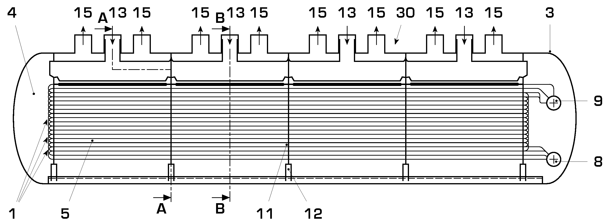
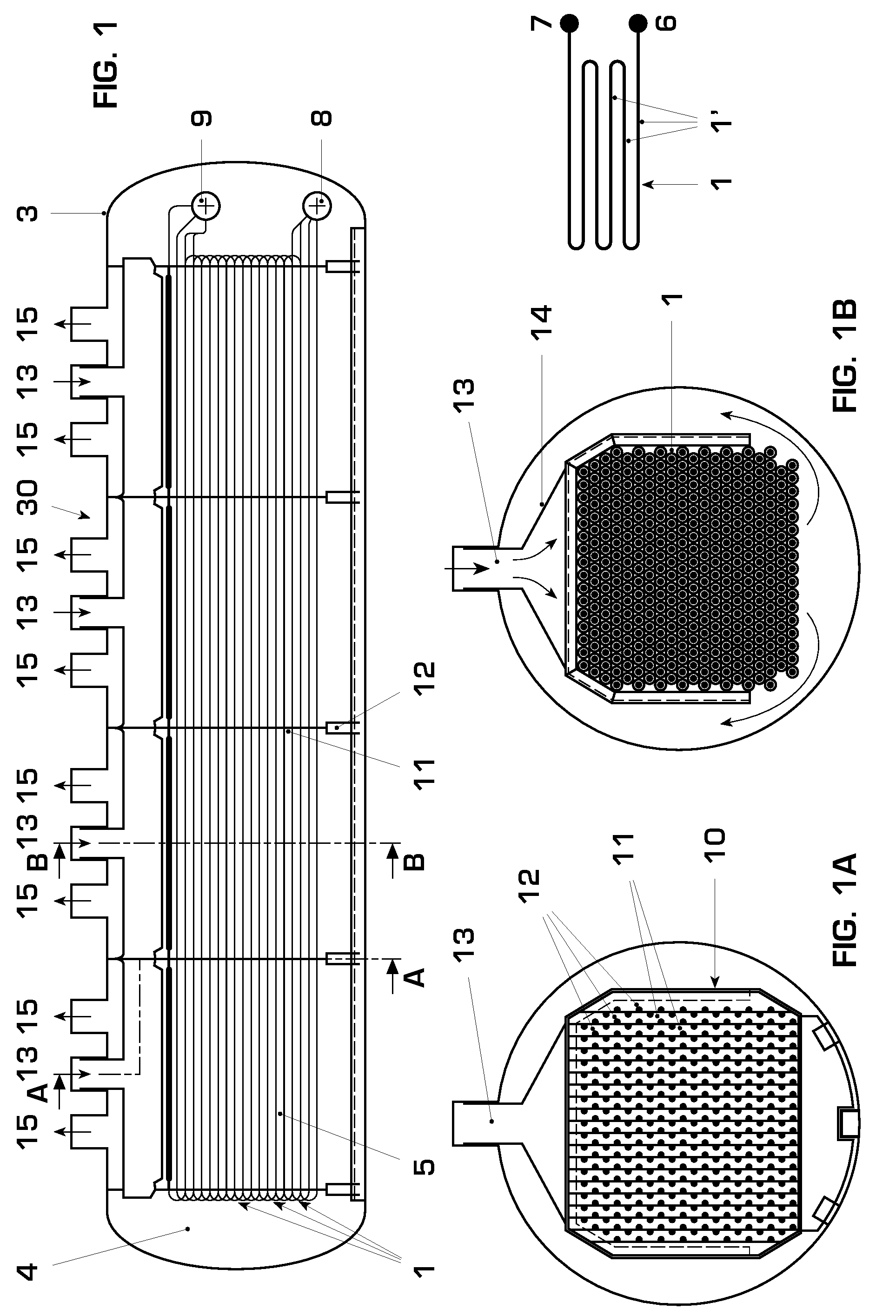
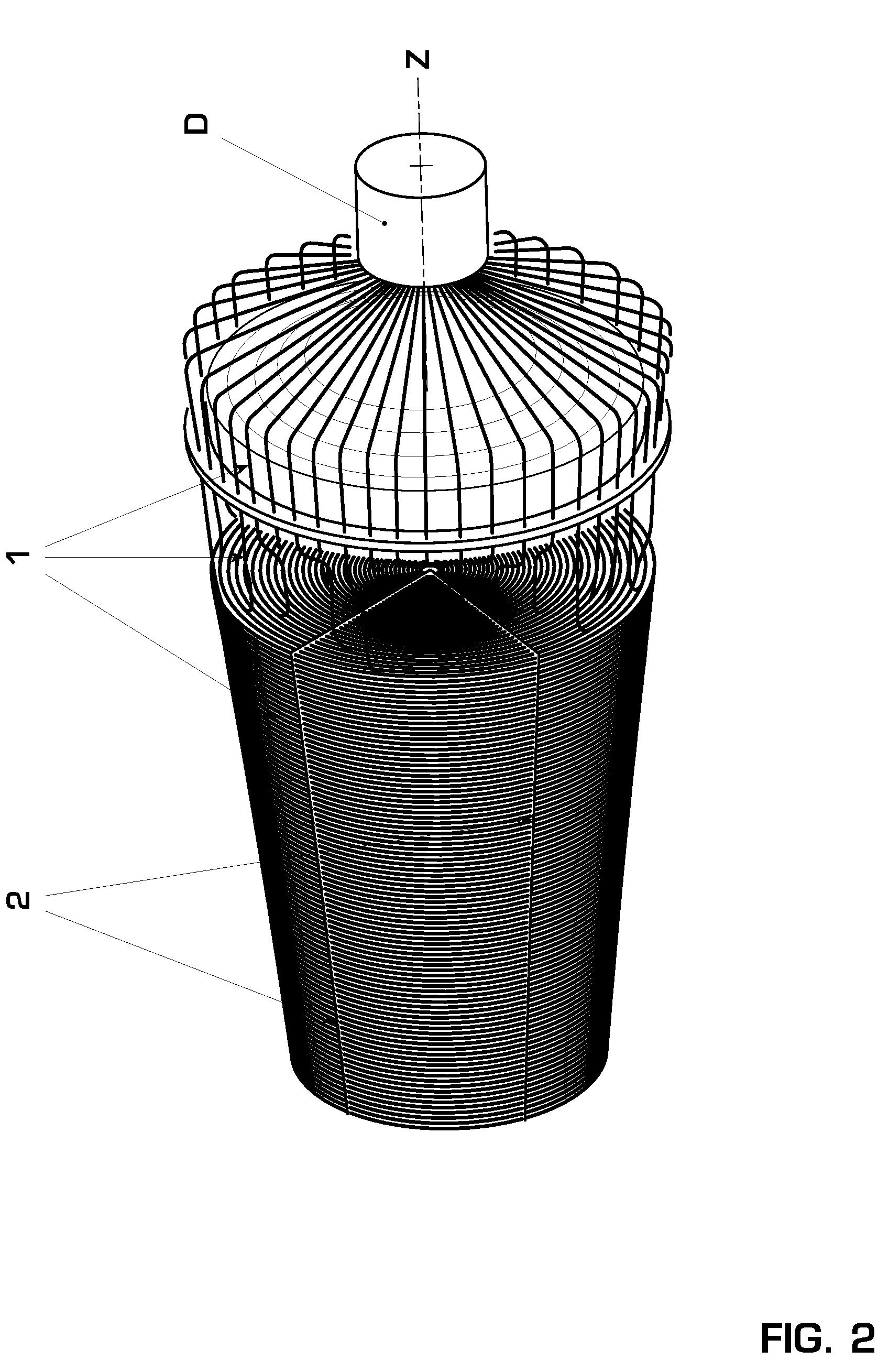
[0022]FIG. 1 shows a longitudinal cross section through a cylindrically formed pressure casing 3, which, in the exemplary embodiment which is shown, has a circular cross section; see also, concerning this, the split drawings according to FIGS. 1A and 1B, which in each case show cross-sectional views along the sectional planes A and B which are drawn in FIG. 1. The pressure casing 3 optionally has a round, oval, or polygonal cross section. The pressure casing 3, which is formed in the fashion of a cylinder, encloses an inner volume 4 in which is introduced a hollow tube arrangement 5 which includes a plurality of individual hollow tubes 1. The hollow tube arrangement 5, which includes a plurality of individual hollow tubes 1, provides for individual hollow tubes 1 which are arranged next to each other, which, in their turn, include a plurality of hollow tube sections 1′ which are arranged vertically above each other, as this is apparent in a very schematized manner from the sub-figur...


PUM


Abstract

A steam generator has a pressure casing formed in the shape of a drum. The longitudinal axis of this pressure casing is oriented horizontally or largely horizontally. A hollow tube (1) is formed in such a way that at least two hollow tube sections (1′) are provided, preferably a plurality of hollow tube sections which extend predominantly parallel to each other, and which are arranged in stack-form vertically or vertically offset above each other, and which in each case are interconnected in pairs at an end section, wherein this hollow tube is located in the vertical direction above the feed section (8).

Description

[0001]This application claims priority under 35 U.S.C. § 119 to German application number 10 2006 015 094.5, filed 31 Mar. 2006, the entirety of which is incorporated by reference herein.BACKGROUND[0002]1. Field of the Invention[0003]The invention relates to a steam generator with a pressure-tight pressure casing which encloses a volume and in which extends at least one hollow tube which is hermetically sealed in relation to the volume, which hollow tube is connected in each case to a feed section and a discharge section which project through the pressure casing in a fluidtight manner, wherein at least one opening for feed of a heat flow into the volume, and also at least one opening for outlet of the heat flow, which engages in thermal interaction with the at least one hollow tube, is provided in the pressure casing.[0004]2. Brief Description of the Related Art[0005]Steam generators of the aforementioned generic type serve preferably for thermal coupling in a combined gas-steam tur...

Claims


Application Information

Patent Timeline
Patent Type & Authority Applications(United States)
IPC IPC(8): F22B1/18F01K7/34
CPCF22B1/18F22B37/14F22B29/064F22B1/1838
Inventor RUCHTI, CHRISTOPH
Owner ALSTOM TECH LTD
Why Eureka
Try Eureka