Nebulizer with flow-based fluidic control and related methods

a fluid control and nebulizer technology, applied in the field of medical devices, can solve the problems of large amount of medication wasted in the environment, difficult to quantify the precise amount of aerosol administered to the patient, and large system size, so as to reduce the inspiratory flow and facilitate the delivery of medication to the patient. the effect of speeding up and/or consistent delivery

Active Publication Date: 2007-10-04
SUNMED GRP HLDG LLC
View PDF6 Cites 53 Cited by
  • Summary
  • Abstract
  • Description
  • Claims
  • Application Information

AI Technical Summary

Benefits of technology

[0008]Therefore, various exemplary embodiments of the invention may provide an improved nebulizer system with a stationary diverter and a flow-based fluidic control system to selectively actuate the nebulization process. There are several advantages of a nebulizer system with a fluidic control system. For example, in addition to its capabilities to overcome one or more problems discussed above, a fluidic control system, being extremely...

Problems solved by technology

Such continuous nebulization causes a significant portion of the medication to be wasted into the environment when the patient is not inhaling.
Also, it may be difficult to quantify the precise amount of aerosol that has been administered to the patient.
These systems, however, are bulky and difficult to set up.
Moreover, studies have shown that a portion of the collected aerosol is deposited or condensed on the inner walls of the reservoir systems without ever being delivered to the patient.
For example, while nebulizers are often intended for ...

Method used


Image

  • Nebulizer with flow-based fluidic control and related methods
  • Nebulizer with flow-based fluidic control and related methods
  • Nebulizer with flow-based fluidic control and related methods

Examples


Embodiment Construction

[0073]Reference will now be made in detail to exemplary embodiments consistent with the present invention, examples of which are illustrated in the accompanying drawings. Wherever possible, the same reference numbers will be used throughout the drawings to refer to the same or like parts.

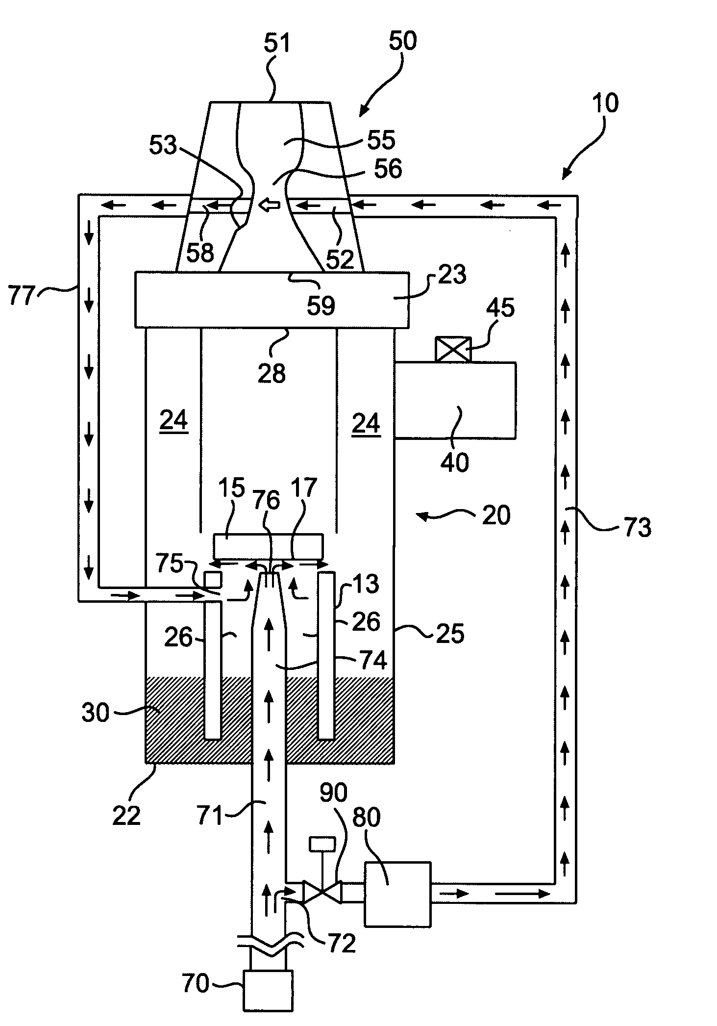
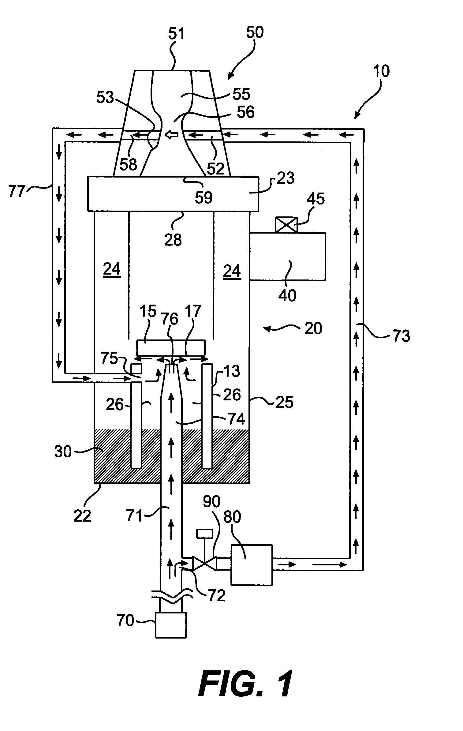
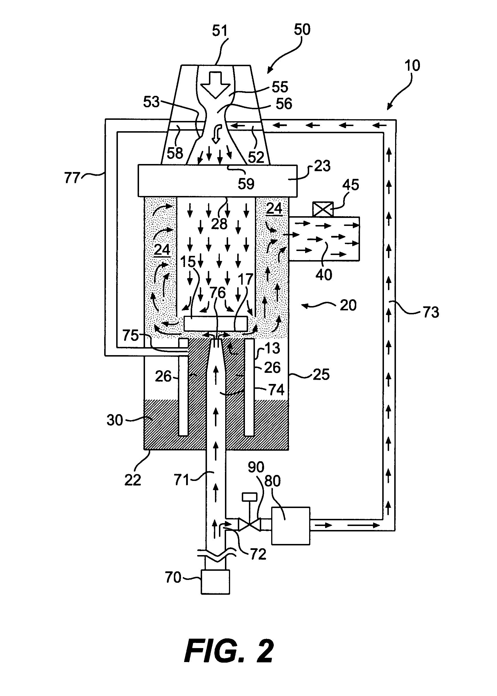
[0074]FIGS. 1 and 2 show a breath-actuated nebulizer 10 with a flow-based fluidic control mechanism, according to an exemplary embodiment of the invention. The nebulizer 10 may comprise a nebulizer body 20 defining an interior space 24 and an aerosol outlet port 40 in fluid communication with the interior space 24 for delivery of nebulized medication to a patient. The nebulizer 10 may also comprise a pressurized gas source 70 (e.g., at approximately 50 psi) for use in generating an aerosol jet during nebulization. As will be explained in more detail below, the fluidic control mechanism may selectively actuate a nebulization process within the nebulizer 10 in response to patient's breath (e.g., patie...


PUM


Abstract

Various embodiments of a breath-activated nebulizer with flow-based fluidic control and related methods of using such a nebulizer are disclosed. The nebulizer may include a body comprising a reservoir for holding medication, a nozzle for emitting a jet of pressurized gas, and a fluid conduit in communication with the reservoir for delivery of the medication proximate the jet to produce an aerosol of medication. The nebulizer may also include a nebulizer outlet in communication with the body for delivery of the aerosol to a patient, an entrainment passage for providing entrainment flow from atmosphere during inhalation by the patient, and a control conduit in fluid communication with the fluid conduit for delivery of a control gas to the fluid conduit to prevent the delivery of the medication proximate the jet. In some exemplary embodiments, the control conduit may comprise a gas passage proximate the entrainment passage to allow the control gas to flow across the entrainment passage. During the inhalation by the patient, the entrainment flow through the entrainment passage may substantially prevent the control gas from flowing across the entrainment passage so as to interrupt the delivery of the control gas to the fluid conduit.

Description

[0001]This application claims the benefit of priority under 35 U.S.C. § 119(e) of U.S. Provisional Application Nos. 60 / 787,195 and 60 / 787,196, both filed Mar. 30, 2006. This application also relates to commonly assigned U.S. application Ser. No. ______ of Steven M. Harrington et al., entitled “NEBULIZER WITH PRESSURE-BASED FLUIDIC CONTROL AND RELATED METHODS” and filed on the same date as the present application. The complete subject matter of each of the above-referenced applications is incorporated by reference herein.FIELD OF THE INVENTION[0002]Embodiments of the present invention relate generally to medical devices and related methods. More specifically, particular embodiments of the invention relate to a nebulizer system with flow-based fluidic control and related methods of using such a system.DESCRIPTION OF RELATED ART[0003]Nebulizers, also known as atomizers, are typically used to treat certain conditions or diseases that require medication to be delivered directly to the re...

Claims


Application Information

Patent Timeline
IPC IPC(8): A61M11/00A61M16/00A61M11/06
CPCA61M11/06A61M15/0091A61M15/002A61M11/002A61M15/0015B05B7/00A61M15/0093A61M15/0096
Inventor HARRINGTON, STEVEN M.GAYLORD, DOUGLASRIVERA, DAVID A.KORNEFF, NEIL A.WILDAY, REBECCA A.ZOLLINGER, CHRIS
Owner SUNMED GRP HLDG LLC
Why Eureka
Try Eureka