Corrugated Hose for Transporting Fluid and Method for Producing the Same

a technology of corrugated hoses and hoses, which is applied in the direction of flexible pipes, mechanical equipment, pipes, etc., can solve the problems of slipping the hose on the mating pipe, the sealing property becomes insufficient, and the resin layer as the barrier layer is hard,

Inactive Publication Date: 2007-10-04
SUMITOMO RIKO CO LTD
View PDF8 Cites 15 Cited by
  • Summary
  • Abstract
  • Description
  • Claims
  • Application Information

AI Technical Summary

Benefits of technology

[0044]As stated above, in the corrugated hose for transporting a fluid according to the present invention, each of the corrugation valleys of the corrugated portion has an inner diameter smaller than an inner diameter of the straight-walled portion, and each of the corrugation hills of the corrugated portion has an outer diameter equal to or smaller than an outer diameter of the straight-walled portion. Therefore, in a production process of the corrugated hose according to the present invention, an unvulcanized tubular hose body (or semivulcanized tubular hose body, hereinafter an explanation on an unvulcanized tubular hose body shall cover a semivulcanized tubular hose body) to of the straight-walled shape can be relatively fitted on the mandrel smoothly without bearing a resistance from the corrugated molding portion formed on the mandrel.
[0055]On the other hand, in the method for producing the corrugated hose according to one aspect of the present invention, another configuration of the mandrel may be used. The mandrel is hollowed out, and has suction channels provided radially through the corrugated molding portion for communication between a hollow portion of the mandrel and an inside of the tubular hose body fitted on the mandrel. And the tubular hose body is suctioned radially inwardly through the suction channels to be deformed into a shape following the contour of the corrugated molding portion of the mandrel, thereby the corrugated portion is formed on the tubular hose body. In this production method, the corrugated portion can be formed successfully or favorably in a certain region of the tubular hose body.

Problems solved by technology

However, the resin layer as the barrier layer is hard since resin is a material harder than rubber.
So, in a hose including the resin layer laminated on an inner side of the outer rubber layer to an extreme end thereof (an axial end of the hose), when the hose is fitted on a mating pipe, a sealing property becomes insufficient due to poor bonding between the mating pipe and the resin layer that defines an inner surface of the hose.
And, since the resin layer defining the inner surface of the hose is hard and has a large deformation resistance, a great force is required for fitting or slipping the hose on the mating pipe.
This causes a problem that easiness of connection of the hose and the mating pipe is impaired.
However, in case of the resin composite hose 200 shown in FIG. 8, such production method cannot be employed.
When an unvulcanized or semivulcanized tubular hose body of straight-walled shape is tried to be relatively fitted on such mandrel in an axial direction, the radially outwardly projecting hill portions impede fitting of the tubular hose body and provide a large resistance during fitting of the tubular hose body.
And, thereby it becomes considerably difficult to fit the tubular hose body on the mandrel.
And, since the tubular hose body that has passed over the hill portions of the corrugated molding portion of the mandrel is diametrically expansively deformed by the hill portions, the tubular hose body is not diametrically contracted sufficiently to return to its original size after passing over the hill portions.
Therefore, it is difficult to form a corrugated hose successfully or favorably in a required shape and size.

Method used


Image

  • Corrugated Hose for Transporting Fluid and Method for Producing the Same
  • Corrugated Hose for Transporting Fluid and Method for Producing the Same
  • Corrugated Hose for Transporting Fluid and Method for Producing the Same

Examples


Embodiment Construction

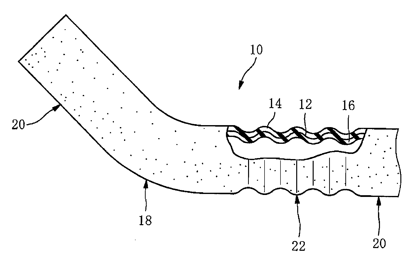
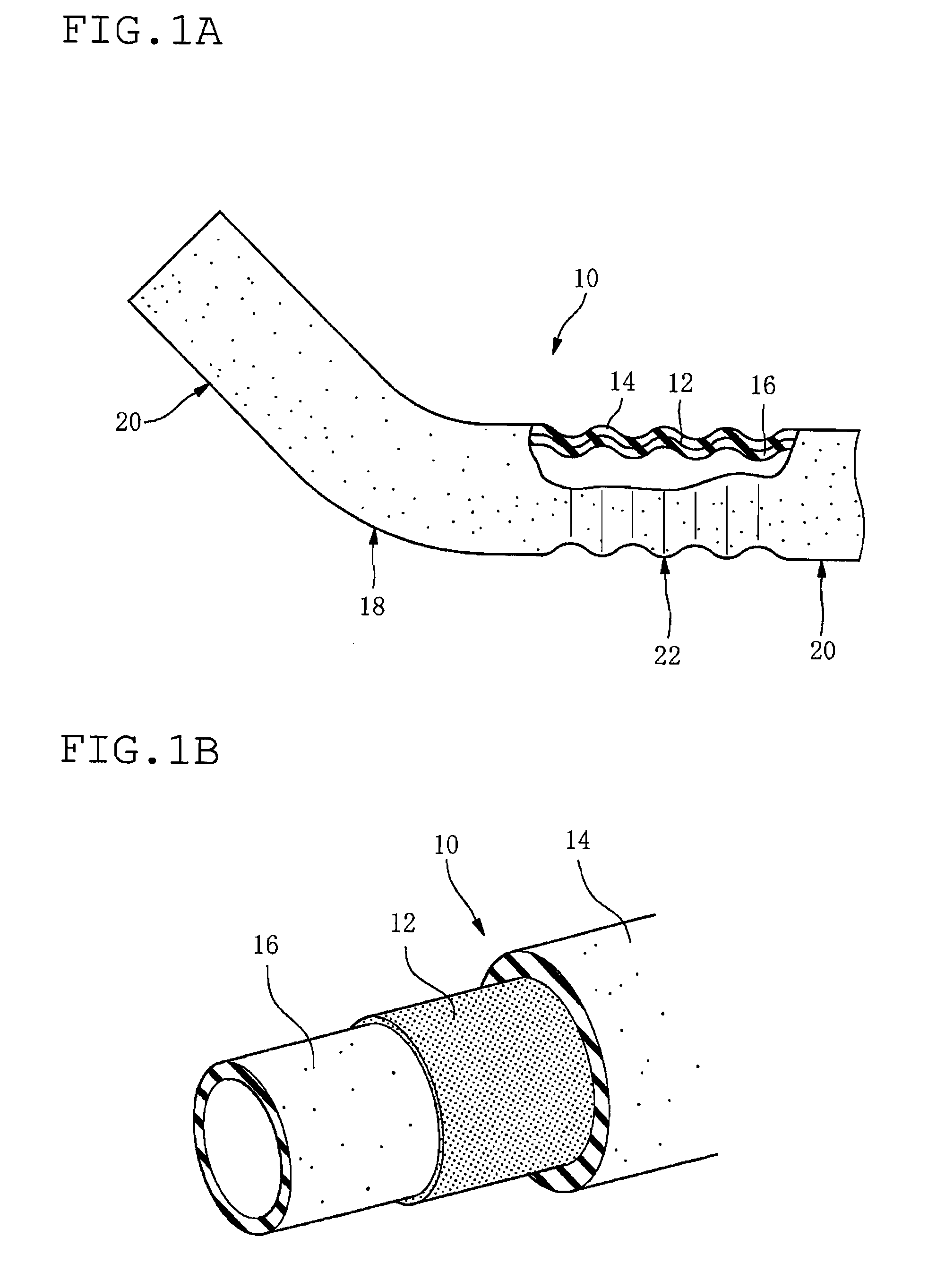
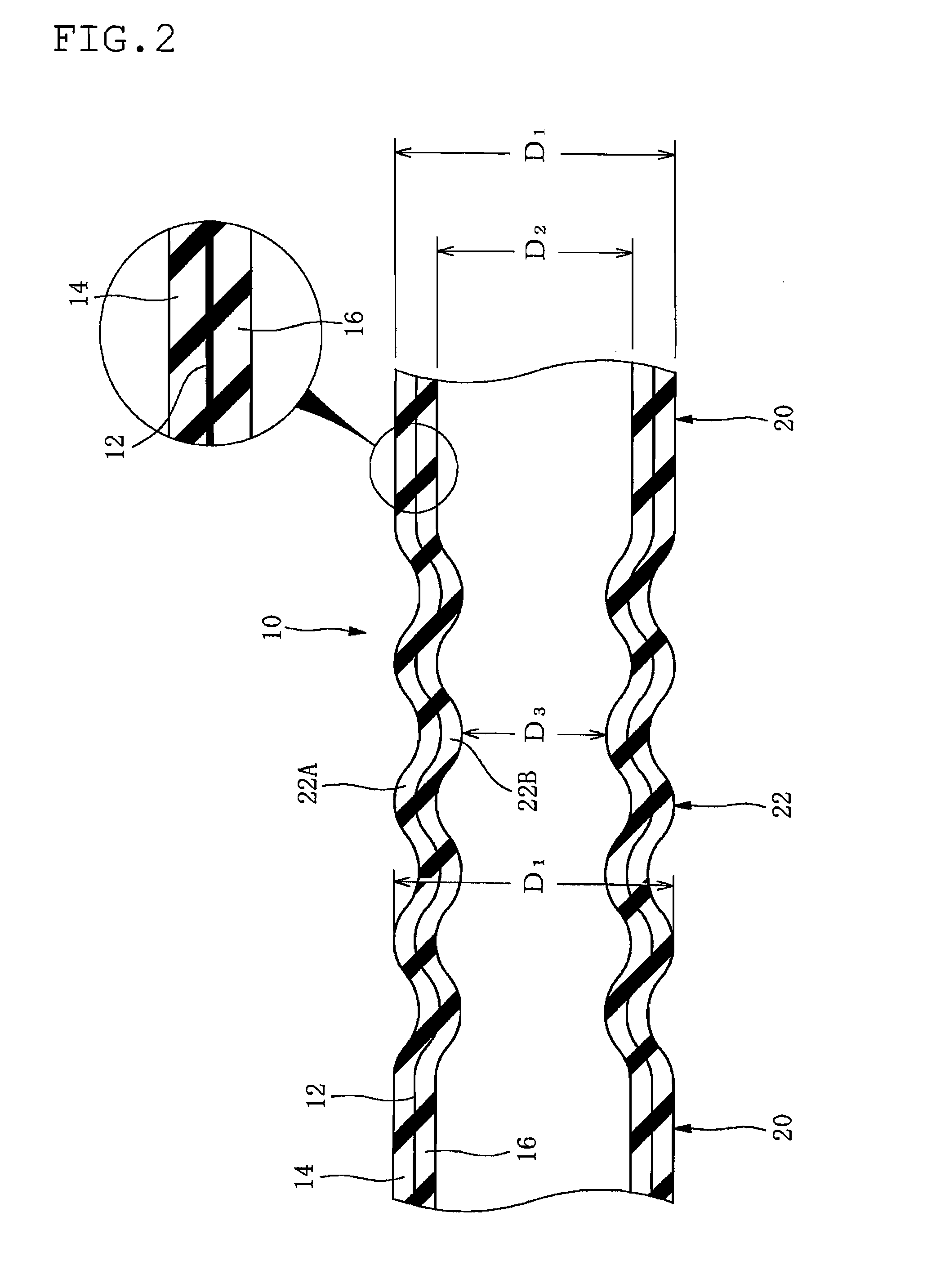
[0071]In FIGS. 1 and 2, numeral reference 10 indicates a corrugated hose for transporting a fluid or a fluid transporting corrugated hose (hereinafter simply referred to as a hose) that is suitable for a hose such as a fuel hose (filler hose) for transporting a fuel injected in a fuel inlet to a fuel tank in a motor vehicle. The hose 10 has a multilayered construction comprising a resin layer 12 as a barrier layer having a permeation resistance to a transported fluid, an outer rubber layer 14 on an outer side of the resin layer 12, and an inner rubber layer 16 as an inner surface layer on an inner side of the resin layer 12.

[0072]Here, the resin layer 12 constituting a middle layer extends through an entire length of the hose, from one end to the other end in an axial direction of the hose 10.

[0073]In this embodiment, the inner rubber layer 16 is made of acrylonitrile butadiene rubber (NBR), the resin layer 12 is made of fluorothermoplastic copolymer consisting of at least three mon...


PUM


Abstract

A corrugated hose for transporting a fluid has a multilayer construction including a resin layer as a barrier layer, an inner rubber layer and an outer rubber layer. The corrugated hose has a straight-walled portion, and a corrugated portion including corrugation valleys and corrugation hills, at least on one axial region of the corrugated hose. Each of the corrugation valleys has an inner diameter smaller than an inner diameter of the straight-walled portion, and each of the corrugation hills has an outer diameter equal to or smaller than an outer diameter of the straight-walled portion thereof.

Description

FIELD OF THE INVENTION[0001]The present invention relates to a corrugated hose for transporting a fluid having at least one corrugated portion on an axial region thereof, specifically, a composite corrugated hose for transporting a fluid with multilayer construction including a resin layer having a permeation resistance to a transported fluid in the middle as a barrier layer, and a method for producing the same.DESCRIPTION OF THE RELATED ART[0002]For application of a fluid transporting hose, for example, a fuel hose in a motor vehicle, a typical rubber hose made of a blend of acrylonitrile-butadiene rubber and polyvinyl chloride (NBR / PVC blend, NBR+PVC) or the like has been conventionally used. Such rubber hose has a high vibration-absorbability, easiness of assembly, and an excellent permeation resistance to a fuel (gasoline).[0003]However, recently, in view of global environmental conservation, regulations on restriction of permeation of motor vehicle fuel has been tightened, and ...

Claims


Application Information

Patent Timeline
Patent Type & Authority Applications(United States)
IPC IPC(8): F16L11/00
CPCF16L11/111
Inventor SAKAZAKI, KAZUSHIGE
Owner SUMITOMO RIKO CO LTD
Why Eureka
Try Eureka