Evaporatively cooled thermosiphon

a technology of thermosiphon and cooling assembly, which is applied in the direction of heat exhanger fins, lighting and heating apparatus, and semiconductor devices, etc., can solve the problems of air having a relatively low heat capacity and the ability of cooling units to effectively disperse heat, so as to increase the surface area, enhance the heat transfer rate, and increase the heat transfer rate

Inactive Publication Date: 2007-10-04
DELPHI TECH INC
View PDF10 Cites 55 Cited by
  • Summary
  • Abstract
  • Description
  • Claims
  • Application Information

AI Technical Summary

Benefits of technology

[0012] The present invention utilizes the series of vapor chambers in the lower boiling portion of the housing interleaved with the series of refrigerant pockets in the upper evaporating portion of the housing to increase the surface area between the lower boiling portion of the housing and the u

Problems solved by technology

These heat exchangers typically use air to directly remove heat from the electronic devices; however air has a relatively low heat capacity.
Additionally, with the d

Method used


Image

  • Evaporatively cooled thermosiphon
  • Evaporatively cooled thermosiphon
  • Evaporatively cooled thermosiphon

Examples


Embodiment Construction

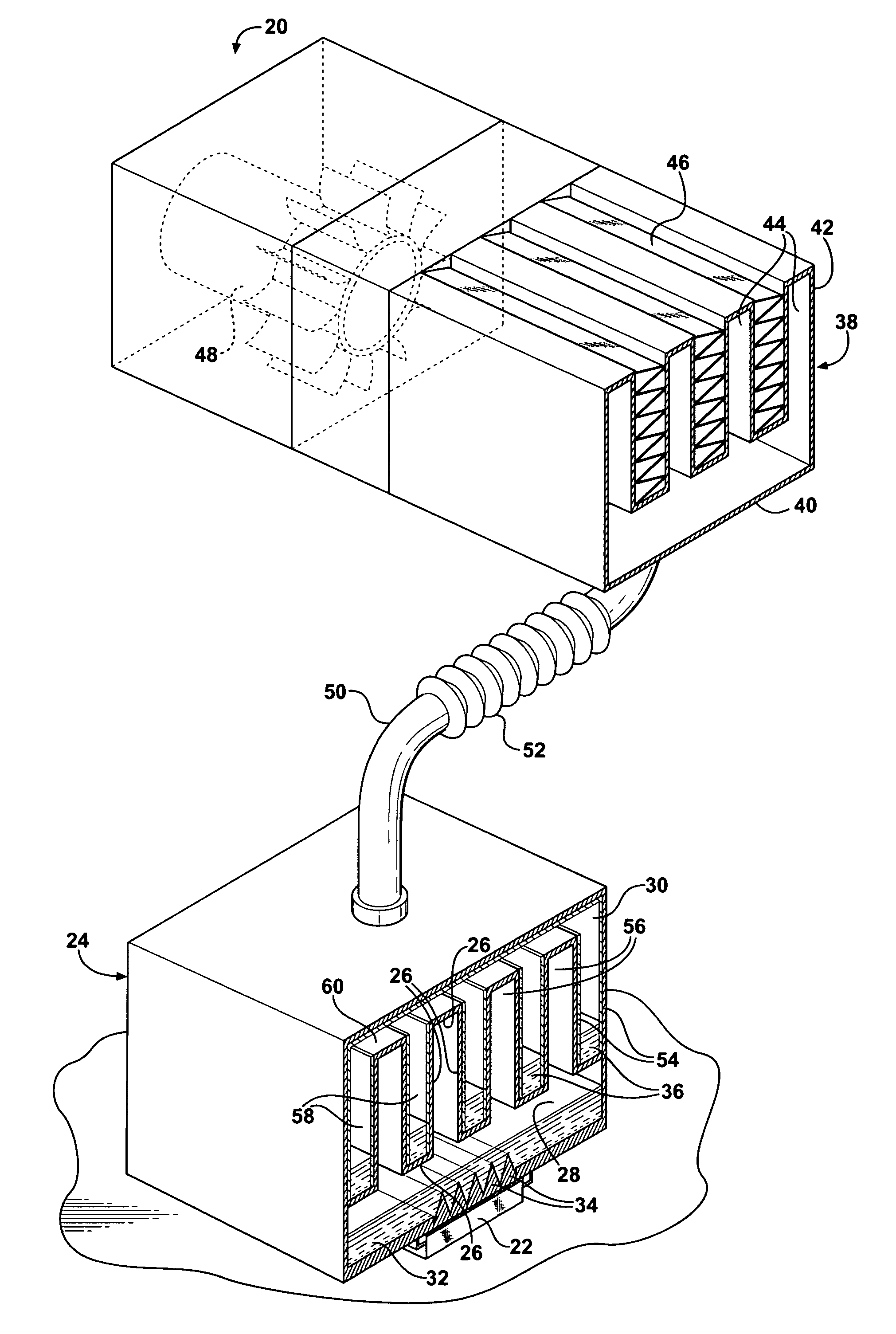
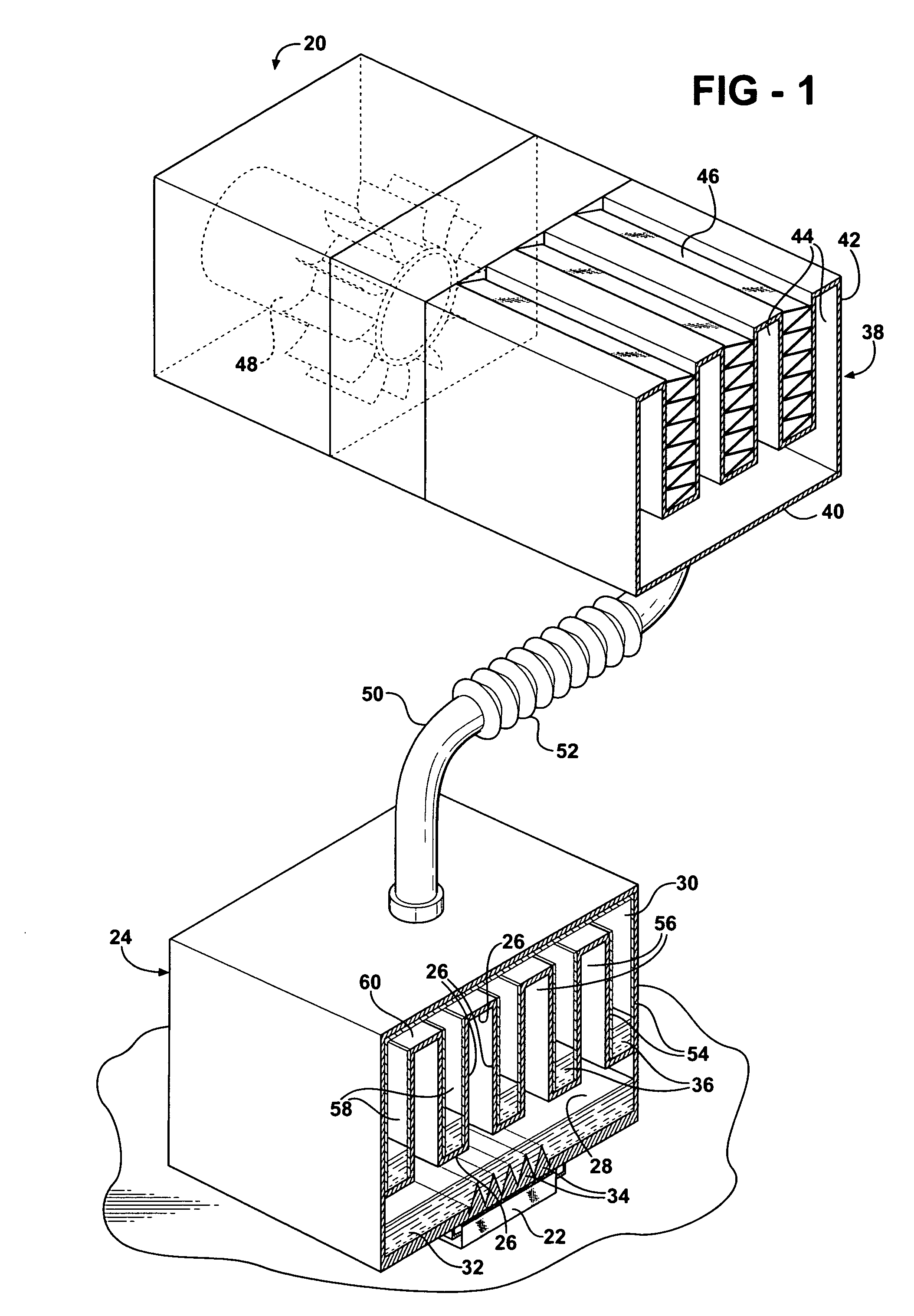
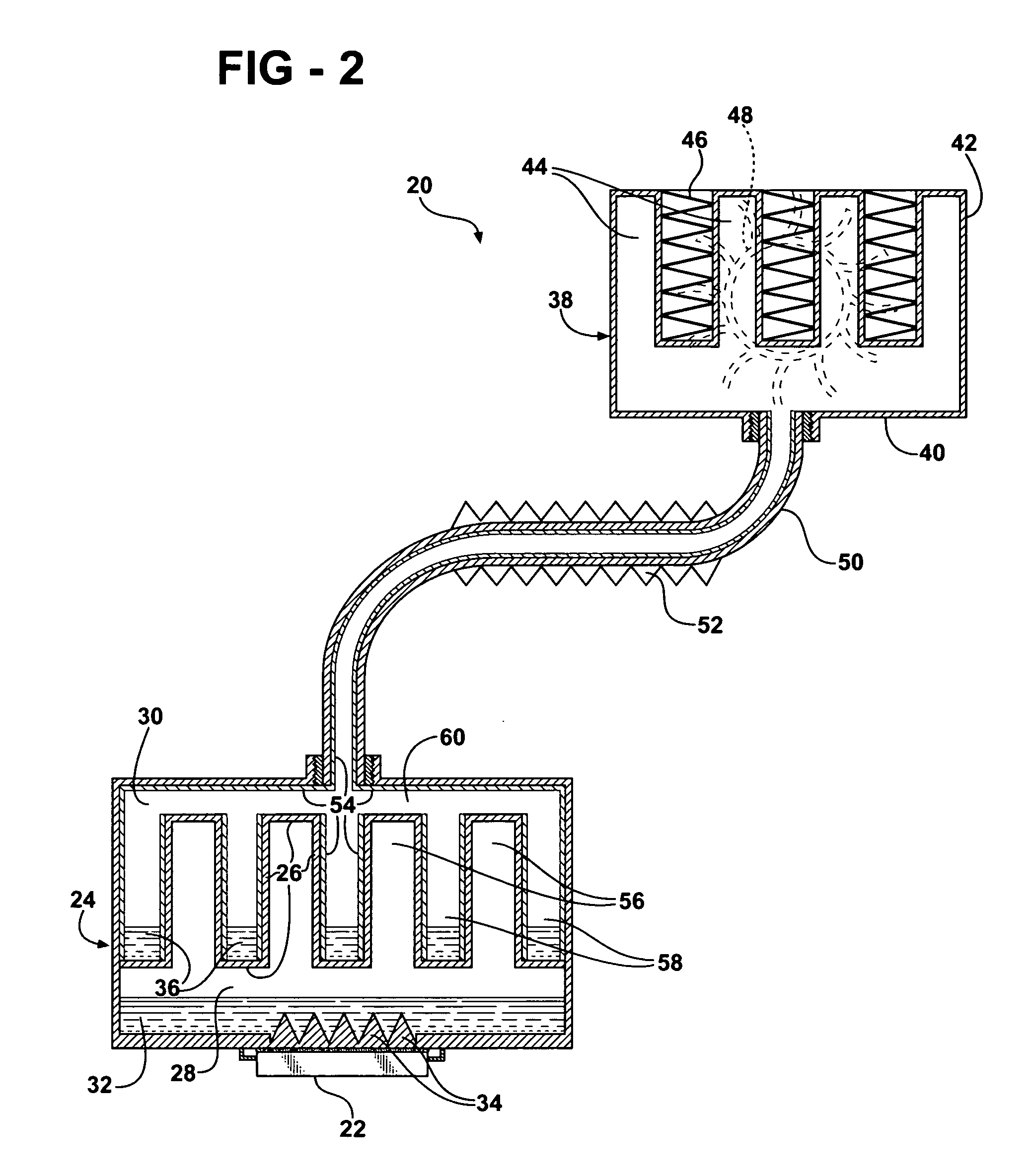
[0017] Referring to the Figures, wherein like numerals indicate corresponding parts throughout the several views, a thermosiphon cooling assembly 20 is shown generally for cooling an electronic device 22.

[0018] A thermosiphon cooling assembly 20 comprises a housing 24 generally indicated having a partition 26 defining a lower boiling chamber 28 for receiving heat from the electronic device 22 and an upper evaporating chamber 30. The assembly 20 is used to cool the electronic device 22 engaging or secured to the exterior of the lower boiling chamber 28 of the housing 24. The housing 24 is generally rectangular with the lower boiling chamber 28 being hermetically sealed to contain a first refrigerant 32 for liquid-to-vapor transformation.

[0019] The first refrigerant 32 is disposed below the partition 26 in the lower boiling chamber 28 of the housing 24 for liquid-to-vapor transformation. The first refrigerant 32 is confined to the lower boiling chamber 28 of the housing 24 and absor...


PUM


Abstract

A thermosiphon cooling assembly cools an electronic device with a first refrigerant disposed in the lower boiling chamber of a housing for liquid-to-vapor transformation and a second refrigerant disposed in an upper evaporating chamber of a housing for liquid-to-vapor transformation. The partition separating the lower boiling chamber of the housing from the upper evaporating chamber of the housing creates a series of vapor chambers within the lower boiling portion for condensing vapor boiled off the first refrigerant. The upper evaporating chamber contains a series of refrigerant pockets interleaved vertically with the vapor chambers to increase the surface area for heat transfer between the refrigerant vapor and the second refrigerant for absorbing heat by the second refrigerant for liquid-to-vapor transformation.

Description

BACKGROUND OF THE INVENTION [0001] 1. Field of the Invention [0002] The subject invention relates to a thermosiphon cooling assembly for cooling an electronic device. [0003] 2. Description of the Prior Art [0004] The operating speed of computers is constantly being improved to create faster and faster computers. With this, comes increased heat generation and a need to effectively dissipate that heat. [0005] Heat exchangers and heat sink assemblies have been used that apply natural or forced convection cooling methods to dissipate heat from electronic devices that are highly concentrated heat sources such as microprocessors and computer chips. These heat exchangers typically use air to directly remove heat from the electronic devices; however air has a relatively low heat capacity. Thus, liquid-cooled units called LCUs employing a cold plate in conjunction with high heat capacity fluids have been used to remove heat from these types of heat sources. Although LCUs are satisfactory for...

Claims


Application Information

Patent Timeline
IPC IPC(8): F28D15/04
CPCF28D15/02F28D15/0266F28F3/048H01L23/427H01L2924/0002F28F2215/00H01L2924/00
Inventor BHATTI, MOHINDER SINGHREYZIN, ILYA
Owner DELPHI TECH INC
Why Eureka
Try Eureka