Superconducting Cable and Method for the Production Thereof

Inactive Publication Date: 2007-10-04
GSI HELMHOLTZZENT FUR SCHWERIONENFORSCHUNG
View PDF9 Cites 6 Cited by
  • Summary
  • Abstract
  • Description
  • Claims
  • Application Information

AI Technical Summary

Benefits of technology

[0035] After those two main components of the hollow cable according to the invention have been produced, the profiled superconducting wires are first brought together to form a longitudinally extended circular bundle around a central cooling channel. In the course of that bringing together, aids such as adhesive substances can also be used in order to ensure a material-based connection between the profiled superconducting wires. That circular bundle comprising profiled superconducting wires is then drawn into the compact outer tube of the superconducting hollow cable. This method has the advantage that the hollow cable can be assembled from two components which can be produced independently of one another.
[0036] In a further method variant, the outer tube is not produced in the form of a compact component but rather is fabricated in two half-shells. On assembly of the superconducting hollow cable, the profiled superconducting wires produced are then placed inside the half-shells. The half-shells are subsequently brought together with profiled superconductors lying inside and welded together. This method has the advantage that, after the welding process, contraction of the outer tube can occur which simultaneously brings about compressive compaction of the profiled superconducting wires lying i

Problems solved by technology

This arrangement of the superconducting wires furthermore results in low cable inductivity and consequently (inter alia) also in reduction of the energy stored.
However, because those cables also increasingly have to overcome higher mechanical and thermal loads in practical use, further development thereof resulted in a high-current cable of the CICC type having as a result of additional

Method used


Image

  • Superconducting Cable and Method for the Production Thereof
  • Superconducting Cable and Method for the Production Thereof
  • Superconducting Cable and Method for the Production Thereof

Examples


first embodiment

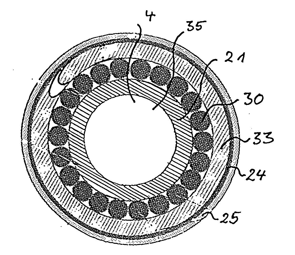
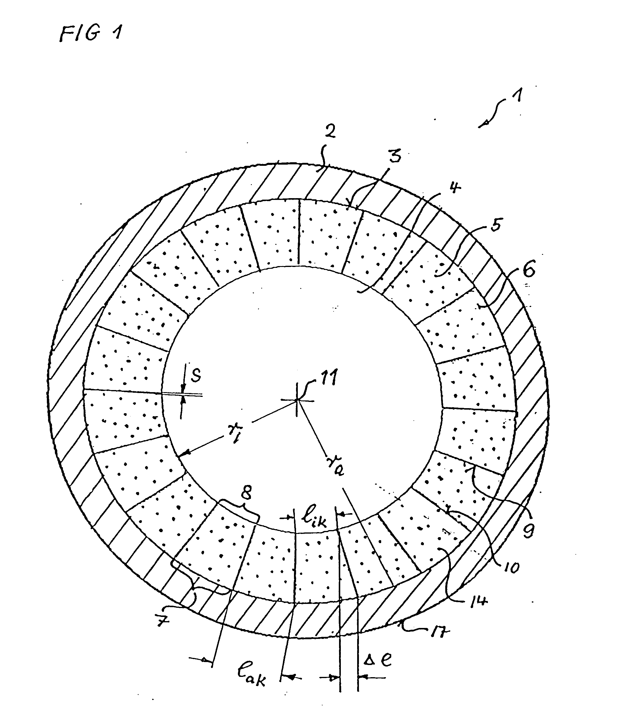
[0096]FIG. 1 shows a cross-section, in diagrammatic form, through a superconducting hollow cable 1 according to the invention. This hollow cable 1 has a central cooling channel 4, which is surrounded by profiled superconducting wires 5, which are usually twisted multifilament wires. In the cross-section shown here, these profiled superconducting wires 5 form a ring directly surrounding the central cooling channel 4 so that those profiled superconducting wires can be intensively cooled by the coolant stream. The profiled superconducting wires 5 are held together by a solidly constructed outer tube 2, which has an inner wall 3, against which the profiled superconducting wires 5 are in close abutment. The profiled superconducting wires 5 have a cross-section which corresponds to a key stone of a Roman bridge and / or of a Gothic vault.

[0097] This profile has an outer region 7 of curvature which is matched to the curvature of the inner wall 3 of the outer tube 2. Furthermore, the cross-se...

second embodiment

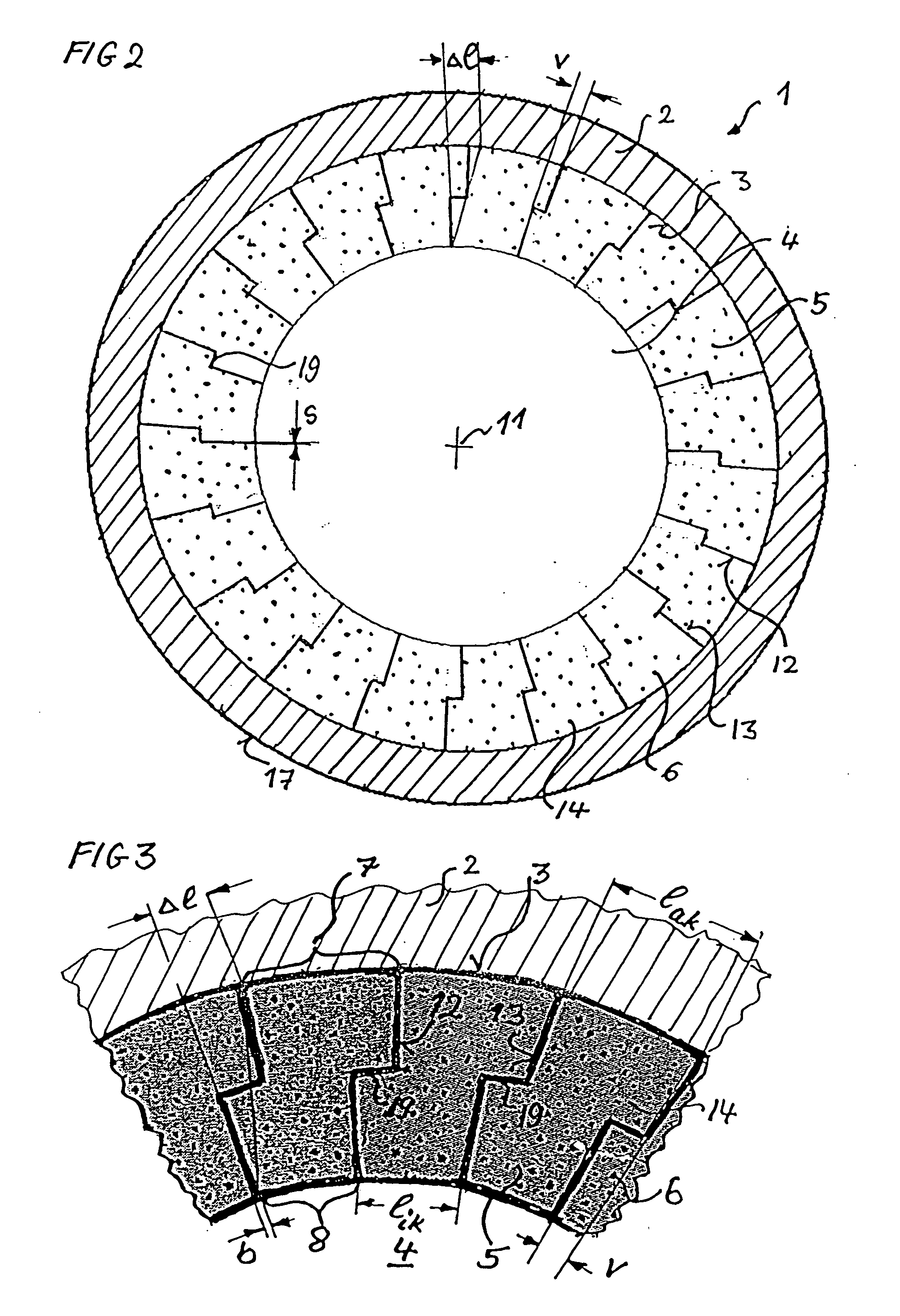
[0104]FIG. 7 shows a cross-section, in diagrammatic form, through a profiled superconducting wire 5 after being provided with a profiled shape for a superconducting cable 1 of the invention according to FIG. 2. Instead of smooth side edges as are still shown in FIG. 6, in the case of this profiling profiled side edges 12 and 13 are shaped or drawn through a drawing block. In the process there are formed stepped shoulders 19, which make possible intermeshing of the profiled superconducting wires 5 when the hollow cable is assembled.

third embodiment

[0105]FIG. 8 shows a cross-section, in diagrammatic form, through a profiled superconducting wire 5 after being provided with a profiled shape for a superconducting hollow cable 1 of the invention according to FIG. 4. This profile too, which has a profile point 20 on the side edge 12, can be obtained by appropriate shaping of an initially circular cross-section as shown in FIG. 5. For the purpose, either four differently shaping profile rollers or a drawing orifice of appropriate shape can be used in order to produce the four profile edges of the cross-section of the profiled superconducting wires 5. An advantage of these profiled superconducting wires 5 of FIG. 8 over FIG. 7 is that an outwardly bulging pointed profile 20 of the profiled side edge 12 is easier to produce by means of profile rollers than is possible for the profile having a stepped shoulder 19 of FIG. 7 and that the intermeshing of those shapes contributes to the profiled superconducting wires' orienting themselves ...


PUM

PropertyMeasurementUnit
Temperatureaaaaaaaaaa
Electrical resistanceaaaaaaaaaa
Coefficient of linear thermal expansionaaaaaaaaaa

Abstract

The present invention relates to a superconducting hollow cable and a method for the production thereof. The superconducting hollow cable (1) has an outer tube (2) which has a circular inner cross-section and a cylindrical inner wall (3). In addition, the superconducting hollow cable (1) has a central cooling channel (4) of a polygonal or circular cross-section that is, however, smaller than the inner cross-section of the outer tube (2). Arranged between the outer tube (2) and the cooling channel (4) are profiled superconducting wires (5). These profiled superconducting wires (5) have a cross-sectional profile which corresponds to a key stone as known for Roman stone bridges or for groin vaults. For the purpose, the cross-sectional profile has at least one outer region (7) of curvature and an inner region (8), the outer region (7) of curvature being matched to the inner radius of the outer tube (2) and the inner region (8) being matched to the cooling channel (4). The side edges (12, 13) too can be profiled either rectilinearly towards the centre-point (11) of the cooling channel (4) or by means of an offset from that rectilinearity.

Description

CROSS-REFERENCE TO RELATED APPLICATIONS [0001] This application is a 371 of PCT / EP2005 / 004420 filed on Apr. 25, 2005, published on Nov. 3, 2005 under publication number WO 2005 / 104143 A1 which claims priority benefits from European Patent Application Number 04009730.5 filed Apr. 23, 2004.BACKGROUND OF THE INVENTION [0002] 1. Field of the Invention [0003] The invention relates to a superconducting hollow cable having an outer tube which has a circular inner cross-section and, consequently, a cylindrical inner wall. In addition, the superconducting hollow cable has a central cooling channel of a circular cross-section that is smaller than the inner cross-section of the outer tube. Arranged between the inner wall of the outer tube and the cooling channel are profiled superconducting wires. Such profiled superconducting wires comprise at least one superconductor (superconducting filament) and have a cross-sectional profile of a key stone as known for Roman stone bridges or for groin vau...

Claims


Application Information

Patent Timeline
IPC IPC(8): H01B12/00H01L39/24H01B12/10H01B12/12
CPCH01B12/10H01B12/12Y10T29/49014Y02E40/641Y02E40/644Y02E40/60
Inventor FISCHER, EGBERTKHODGHIBAGIYAN, HAMLETKOVALENKO, ALEXANDERMORITZ, GEBHARD
Owner GSI HELMHOLTZZENT FUR SCHWERIONENFORSCHUNG
Why Eureka
Try Eureka