Method and Apparatus for Electrically Connecting Two Substrates Using a Resilient Wire Bundle Captured in an Aperture of an Interposer by a Retention Member

a technology interposers, which is applied in the direction of coupling device connections, fixed connections, coupling device details, etc., can solve the problems of catastrophic damage to one or both of the electronic substrates being interconnected, loosening and falling out of the interposer, so as to improve the retention of resilient wire bundles

Inactive Publication Date: 2007-10-04
BRODSKY WILLIAM LOUIS +4
View PDF10 Cites 45 Cited by
  • Summary
  • Abstract
  • Description
  • Claims
  • Application Information

AI Technical Summary

Benefits of technology

[0013] According to the preferred embodiments of the present invention, two substrates are electrically connected using resilient wire bundles captured in apertures of an interposer by a retention member. The interposer comprises an electrically non-conductive carrier having two surfaces and apertures extending from surface to surface. A resilient wire bundle is disposed in each aperture. An electrically non-conductive retention member, such as a thin polyimide film, is associated with one or both surfaces of the carrier and has an orifice overlying each aperture. The width of each orifice is smaller than that of the underlying aperture to thereby enhance retention of the resilient wire bundle within the aperture. Pin contacts of one or both of the substrates make electrical contact with the resilient wire bundles by extending through the orifices of the retention member and partially through the apertures. In one embodiment of the present invention, the interposer is a land grid array (LGA) connector that connects an electronic module and a printed circuit board (PCB).

Problems solved by technology

A well known problem with electrical connectors that incorporate resilient wire bundles is that one or more of the resilient wire bundles may be jarred loose and fall out from the interposer during transit or handling.
In a related problem, instead of being jarred completely out of the interposer, the resilient wire bundle is instead jarred partially loose from the interposer such that when the resilient wire bundle is compressed between the two electronic substrates, the resilient wire bundle bends over and makes contact with an adjacent resilient wire bundle or an adjacent contact on the electronic substrate.
If a bent-over resilient wire bundle makes such an inadvertent contact, a short circuit will result.
Such a short can catastrophically damage to one or both of the electronic substrates being interconnected.
However, one or more of the shaping dies may insufficiently deform the resilient wire bundles and thereby fail to prevent same from being dislodged.
Also, the shaping dies may inconsistently deform the resilient wire bundles (i.e., some shaping dies will under-penetrate the resilient wire bundles while other shaping dies will over-penetrate).
Another problem with electrical connectors that incorporate resilient wire bundles is that the strands of the resilient wire bundles are not very robust.
For example, the strands of resilient wire bundles are prone to spreading or “mushrooming” upon repeated insertions.
This occurs because mushrooming can undesirably limit the compressive force on the resilient wire bundle and thereby increase electrical resistance through the resilient wire bundle to the point where an open circuit or near-open circuit is created.
Moreover, the strands of resilient wire bundles can snag on mating features during insertion and withdrawals.
If either a snagged strand of a resilient wire bundle or a mushroomed resilient wire bundle subsequently makes contact with an adjacent resilient wire bundle or an adjacent contact on the electronic substrate, a short circuit will result.
Such a short can catastrophically damage to one or both of the electronic substrates being interconnected.

Method used


Image

  • Method and Apparatus for Electrically Connecting Two Substrates Using a Resilient Wire Bundle Captured in an Aperture of an Interposer by a Retention Member
  • Method and Apparatus for Electrically Connecting Two Substrates Using a Resilient Wire Bundle Captured in an Aperture of an Interposer by a Retention Member
  • Method and Apparatus for Electrically Connecting Two Substrates Using a Resilient Wire Bundle Captured in an Aperture of an Interposer by a Retention Member

Examples


Embodiment Construction

[0023] 1.0 Overview

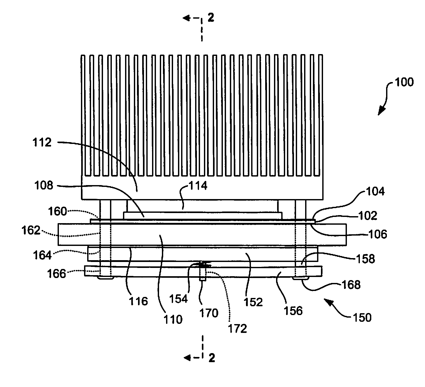
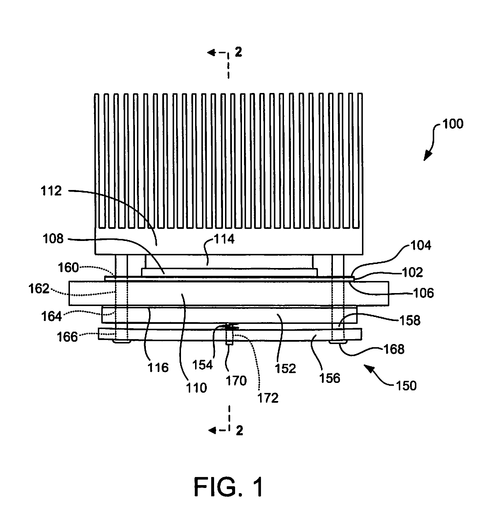
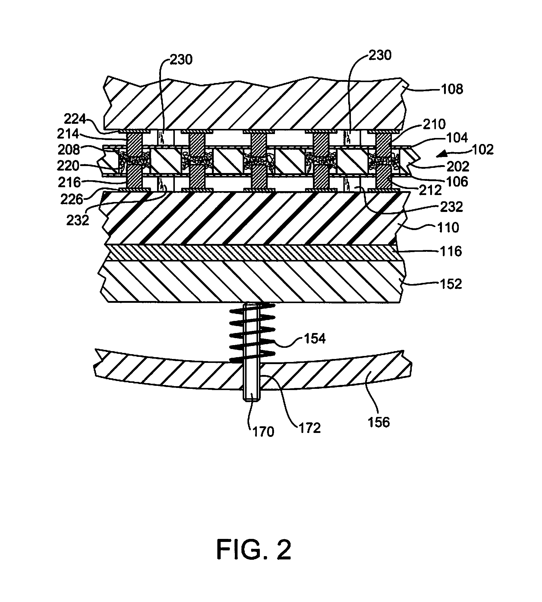
[0024] In accordance with the preferred embodiments of the present invention, two subtrates are electrically connected using resilient wire bundles captured in apertures of an interposer by a retention member. The interposer comprises an electrically non-conductive carrier having two surfaces and apertures extending from surface to surface. A resilient wire bundle is disposed in each aperture. An electrically non-conductive retention member, such as a thin polyimide film, is associated with one or both surfaces of the carrier and has an orifice overlying each aperture. The width of each orifice is smaller than that of the underlying aperture to thereby enhance retention of the resilient wire bundle within the aperature. Pin contacts of one or both of the substrates make electrical contact with the resilient wire bundles by extending through the orifices of the retention member and partially through the apertures. In one embodiment of the present invention, the in...


PUM

PropertyMeasurementUnit
thicknessaaaaaaaaaa
diameteraaaaaaaaaa
thicknessaaaaaaaaaa

Abstract

A method and apparatus for electrically connecting two substrates using resilient wire bundles captured in apertures of an interposer by a retention film. The interposer comprises an electrically non-conductive carrier having two surfaces and apertures extending from surface to surface. A resilient wire bundle is disposed in each aperture. An electrically non-conductive retention film is associated with one or both surfaces of the carrier and has an orifice overlying each aperture. The width of each orifice is smaller than that of the underlying aperture to thereby enhance retention of the resilient wire bundle within the aperture. Pin contacts of one or both of the substrates make electrical contact with the resilient wire bundles by extending through the orifices of the retention film and partially through the apertures. In one embodiment, the interposer is a land grid array (LGA) connector that connects an electronic module and a printed circuit board (PCB).

Description

CROSS-REFERENCE TO RELATED APPLICATION [0001] This patent application is a continuation application of U.S. patent application Ser. No. 11 / 297,307 (docket no. ROC920050235US1), filed Dec. 8, 2005, entitled “METHOD AND APPARATUS FOR ELECTRICALLY CONNECTING TWO SUBSTRATES USING A RESILIENT WIRE BUNDLE CAPTURED IN AN APERTURE OF AN INTERPOSER BY A RETENTION MEMBER”, which is hereby incorporated by reference.BACKGROUND OF THE INVENTION [0002] 1. Field of Invention [0003] The present invention relates in general to the electrical connector field. More particularly, the present invention relates to the assembly of electrical connectors incorporating an interposer having a resilient wire bundle that provides a conductive path between two substrates and that is captured within an aperture of the interposer by a retention member. The present invention also relates to apparatus involved in the assembly of such electrical connectors. [0004] 2. Background Art [0005] Electrical connectors are in...

Claims


Application Information

Patent Timeline
Patent Type & Authority Applications(United States)
IPC IPC(8): H01R12/00H05K1/03
CPCH01R13/2407H01R23/688Y10T29/49126Y10T29/49208H01R12/52Y10T29/49117Y10T29/4913Y10T29/49204Y10T29/49155Y10T29/49169
Inventor BRODSKY, WILLIAM LOUISCOLBERT, JOHN LEEHAMILTON, ROGER DUANEMIKHAIL, AMANDA ELISA ENNISPLUCINSKI, MARK DAVID
Owner BRODSKY WILLIAM LOUIS
Why Eureka
Try Eureka