Nucleic acid detection device

a detection device and nucleic acid technology, applied in the field of nucleic acid detection devices, can solve the problems of reducing detection accuracy, cumbersome operation, and requiring an expensive apparatus to detect fluorescent dyes,

Active Publication Date: 2007-10-04
TOSHIBA MEDICAL SYST CORP
View PDF10 Cites 7 Cited by
  • Summary
  • Abstract
  • Description
  • Claims
  • Application Information

AI Technical Summary

Benefits of technology

[0011]A nucleic acid detection device according to the present invention comprises a flow channel that allows a solution containing a nucleic acid recognition body to flow through it, probe electrodes having immobilized nucleic acid probes, and a counter electrode used to measure an electrochemical response of the nucleic acid recognition body. The flow channel includes a curved portion and a straight portion that is continued from and located downstream of the curved portion. The counter electrode is pr

Problems solved by technology

The former method can perform detection only at limited locations and requires cumbersome operation.
The latter method req

Method used


Image

  • Nucleic acid detection device
  • Nucleic acid detection device
  • Nucleic acid detection device

Examples


first embodiment

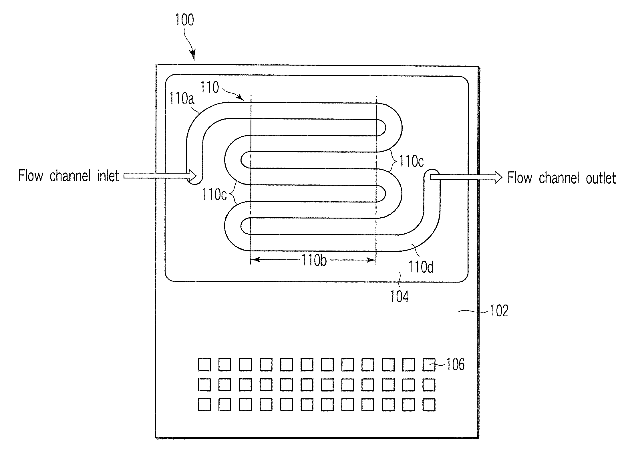
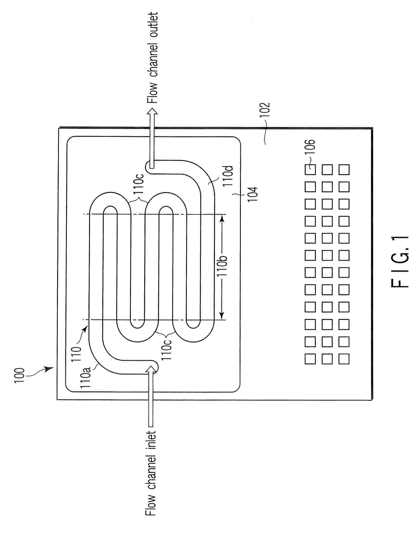
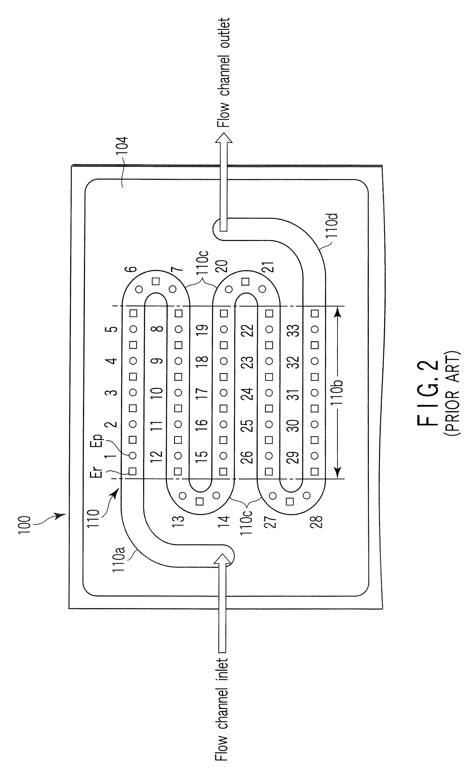
[0040]As shown in FIG. 4, a nucleic acid detection device 100 according to this embodiment has probe electrodes Ep and auxiliary electrodes Er. All the probe electrodes Ep are arranged at straight portions 110b. In other words, the probe electrodes Ep are arranged so as to avoid curved portions 110c. The auxiliary electrodes Er are arranged at the two ends of the row of the probe electrodes Ep located on each straight portion 110b and among the probe electrodes Ep.

[0041]Although the probe electrodes Ep and the auxiliary electrodes Er are arranged at regular intervals, they need not be arranged at regular intervals, but may be arranged at irregular intervals.

[0042]The auxiliary electrodes Er located at the two sides of each row of the probe electrodes Ep are located outside the corresponding straight portion 110b. Namely, the auxiliary electrodes Er at the two sides are located at the flow channel inlet 110a, the curved portions 110c, or the flow channel outlet 110d.

[0043]In this nu...

second embodiment

[0056]As shown in FIG. 10, a nucleic acid detection device 100 according to this embodiment has probe electrodes Ep and auxiliary electrodes Er, as in the first embodiment. All the probe electrodes Ep are arranged at straight portions 110b. The auxiliary electrodes Er are arranged at the two ends of the row of the probe electrodes Ep located on each straight portion 110b.

[0057]In this embodiment as well, preferably, the probe electrodes Ep are arranged so as to avoid the curved portions 110c and the upstream ends of the straight portions 110b that are located within a distance L from the downstream end of the curved portion 110c.

[0058]The auxiliary electrodes Er are located outside the straight portions 110b. More specifically, the auxiliary electrodes Er on the two sides are located at the flow channel inlet 110a, the curved portions 110c, or the flow channel outlet 110d. The auxiliary electrodes Er may be located at the portions of the straight portions 110b that are within the ...

third embodiment

[0063]As shown in FIG. 11, a nucleic acid detection device 100 according to this embodiment has probe electrodes Ep and auxiliary electrodes Er, as in the first embodiment. All the probe electrodes Ep are arranged at straight portions 110b. More preferably, the probe electrodes Ep are arranged so as to avoid the curved portions 110c and the upstream ends of the straight portions 110b that are located within a distance L from the downstream end of the curved portion 110c.

[0064]The auxiliary electrodes Er are arranged so as to avoid the straight portions 110b. Hence, the auxiliary electrodes Er are located somewhere within the flow channel inlet 110a, the curved portions 110c, and the flow channel outlet 110d.

[0065]The auxiliary electrodes Er located on the left side are commonly connected to one auxiliary electrode pad 106r through one auxiliary electrode wiring 108r. Similarly, the auxiliary electrodes Er located on the right side are commonly connected to another auxiliary electr...


PUM

PropertyMeasurementUnit
Flow rateaaaaaaaaaa
Distanceaaaaaaaaaa
Electrochemical propertiesaaaaaaaaaa

Abstract

A nucleic acid detection device includes a flow channel through which a solution containing a nucleic acid recognition body flows, probe electrodes having immobilized nucleic acid probes, and a counter electrode used to measure an electrochemical response of the nucleic acid recognition body. The flow channel includes a curved portion and a straight portion continued from and located downstream of the curved portion. The probe electrodes are arranged at intervals along the straight portion, avoiding an upstream end of the straight portion that is located within a distance L from the curved portion. The distance L is given by L=0.065×Re×D, Re=ρuD/μ, and D=4 S/Lp where ρ, u, and μ are a concentration, a flow velocity, and a viscosity of the solution, and S and Lp are a sectional area and a wall peripheral perimeter of the flow channel, respectively.

Description

CROSS-REFERENCE TO RELATED APPLICATIONS[0001]This application is based upon and claims the benefit of priority from prior Japanese Patent Application No. 2006-092030, filed Mar. 29, 2006, the entire contents of which are incorporated herein by reference.BACKGROUND OF THE INVENTION[0002]1. Field of the Invention[0003]The present invention relates to a nucleic acid detection device used to a target nucleic acid detection utilizing the electrochemical response of a nucleic acid recognition body.[0004]2. Description of the Related Art[0005]As genetic engineering develops in recent years, disease diagnosis or prevention using a gene has become possible in the medical field. This is called gene diagnosis. Detecting a human gene defect or change that causes a disease allows the disease to be diagnosed or predicted precritically or at its very early stage. Along with human genome decoding, researches on the relationship between the genotype and disease advance. Treatments that match the gen...

Claims


Application Information

Patent Timeline
IPC IPC(8): G01N33/487
CPCB01L3/5027B01L2300/0636G01N27/3275B01L2300/0883B01L2300/0645
Inventor OKADA, JUNHONGO, SADATOGEMMA, NOBUHIRO
Owner TOSHIBA MEDICAL SYST CORP
Why Eureka
Try Eureka