
Low voltage triggering silicon controlled rectifier and circuit thereof

a technology of low-voltage triggering and rectifiers, which is applied in the direction of diodes, transistors, semiconductor devices, etc., can solve the problems of inability to shut off latch-up conditions, inability to apply esd protection apparatuses with low-holding-voltage scr to power supply protection, and the latch-up off problem

Inactive Publication Date: 2007-10-04
ADVANCED ANALOG TECH INC
View PDF3 Cites 19 Cited by
  • Summary
  • Abstract
  • Description
  • Claims
  • Application Information

AI Technical Summary

Benefits of technology

[0013] The objective of the present invention is to provide a low voltage triggering silicon controlled rectifier (LVTSCR), which utilizes a resistor between the anode of the LVTSCR and the emitter of the parasitical PNP bipolar transistor thereof to increase the holding voltage thereof and leave the triggering voltage thereof unchanged. The LVTSCR is fabricated with a 0.6 pm CMOS technology and exhibits a triggering voltage below 15 volts.

Problems solved by technology

The SCR or a circuit protected by the SCR, which is fabricated by CMOS manufacturing processes, may utilize a source voltage larger than the holding voltage of the SCR and results in a latch-up off problem.
That is, the inability to shut off the latch-up condition after the ESD event or after a power surge or spike in the circuit.
Thus, the ESD protection apparatus with a low holding voltage SCR cannot be applied for power supply protection.

Method used


Image

  • Low voltage triggering silicon controlled rectifier and circuit thereof
  • Low voltage triggering silicon controlled rectifier and circuit thereof
  • Low voltage triggering silicon controlled rectifier and circuit thereof

Examples


Embodiment Construction

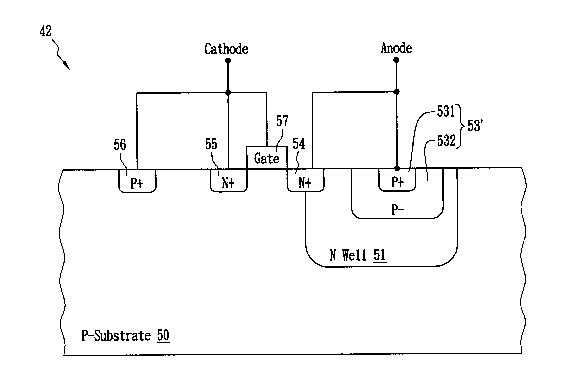
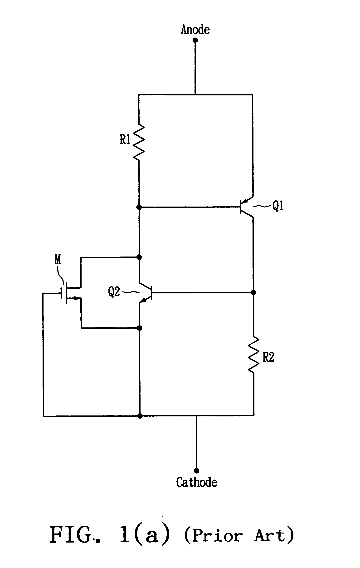
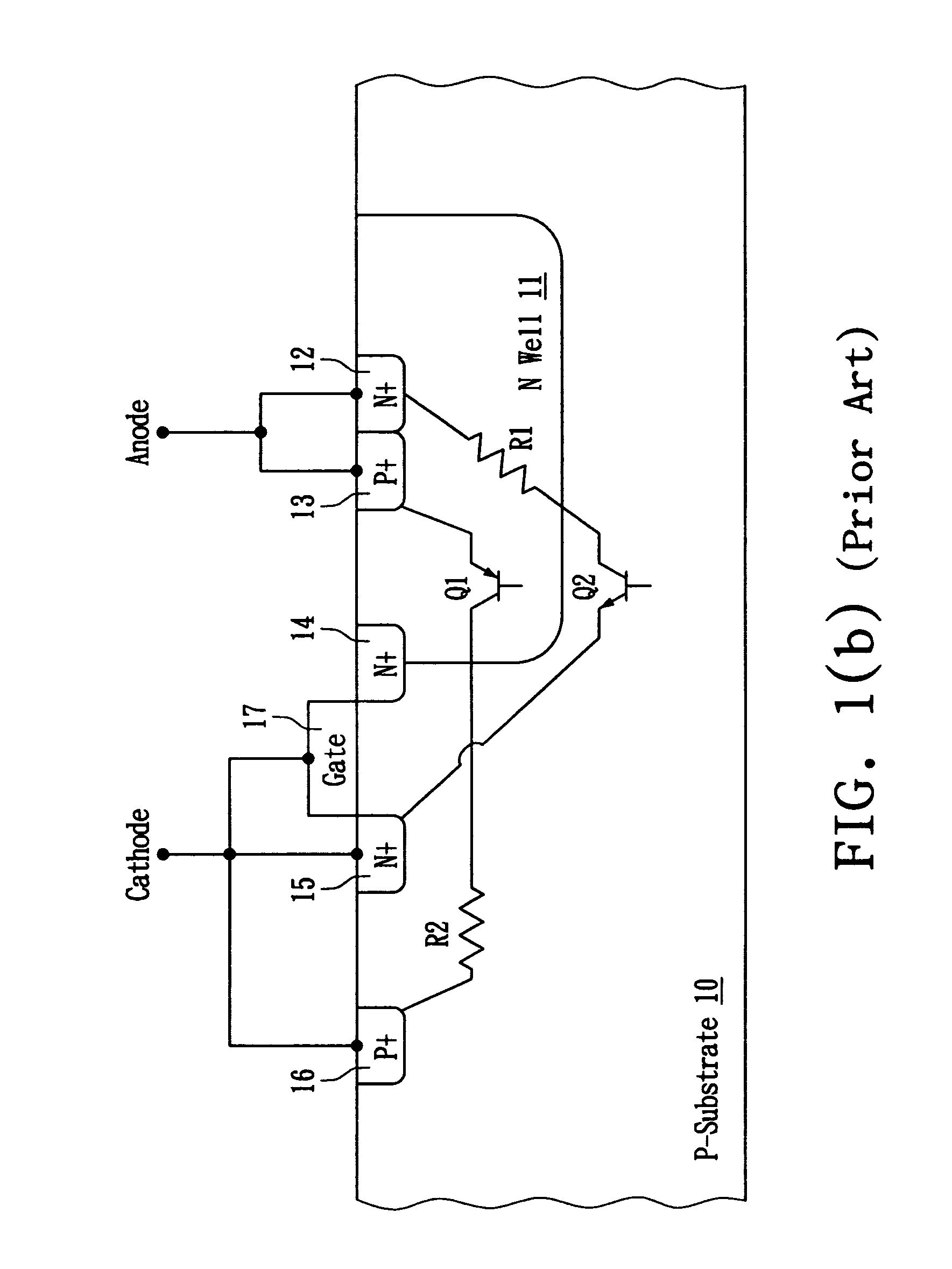
[0026]FIG. 2 is the equivalent circuit of the low voltage triggering silicon controlled rectifier (LVTSCR) of the present invention, which is based on the circuit of FIG. 1(a) and adds a resistor R3 between the anode and the parasitical bipolar PNP transistor Q1 of FIG. 1(a). The equivalent circuit of the LVTSCR of the present invention comprises a first resistor R1, a second resistor R2, a third resistor R3, a first transistor Q1, a second transistor Q2, and a third transistor M. The third resistor R3 is used to increase the holding voltage of the LVTSCR. The emitter, the collector, and the base of the first transistor Q1 are electrically connected to the anode (i.e., a first node) through the third resistor R3, to the cathode (i.e., a second node) through the second resistor R2, and to the anode through the first resistor R1, respectively. The base, the emitter, and the collector of the second transistor Q2 are electrically connected to the collector of the first transistor Q1, to...


PUM


Abstract

A low voltage triggering silicon controlled rectifier (LVTSCR) is disclosed. The LVTSCR utilizes an added resistor disposed in a second doped region between the anode of the LVTSCR and the emitter of the parasitical bipolar PNP transistor to increase the holding voltage thereof when the LVTSCR is triggered. The LVTSCR includes a semiconductor substrate with a first conductive type and a gate. The semiconductor substrate includes a first doped region with a second conductive type, a second doped region with the first conductive type, a third doped region with the second conductive type, a fourth doped region with the second conductive type and a fifth doped region with the first conductive type. The gate is applied with a lower triggering voltage to trigger the LVTSCR.

Description

RELATED U.S. APPLICATIONS [0001] Not applicable. STATEMENT REGARDING FEDERALLY SPONSORED RESEARCH OR DEVELOPMENT [0002] Not applicable. REFERENCE TO MICROFICHE APPENDIX [0003] Not applicable. FIELD OF THE INVENTION [0004] The present invention relates to a low voltage triggering silicon controlled rectifier (LVTSCR) and a circuit thereof, and more particularly, to a low voltage triggering silicon controlled rectifier and a circuit thereof with high holding voltage and low triggering voltage. BACKGROUND OF THE INVENTION [0005] The issue of electrostatic discharge (ESD) is common in the manufacturing and use of integrated circuits (ICs). With rapid growth in demand for high-speed computation and broadband wireless communication products, and the reduction in size of current integrated circuits from 80 nanometers down to 65 nanometers, the elements in an IC become tiny and sensitive to instant electrostatic discharge. Therefore, the quality of ICs is seriously influenced by the ESD; an...

Claims


Application Information

Patent Timeline
Patent Type & Authority Applications(United States)
IPC IPC(8): H01L29/74
CPCH01L29/87H01L27/0262
Inventor YANG, SHENG YUANFANG, CHENG YU
Owner ADVANCED ANALOG TECH INC
Learn More