
Supplemental side impact protection system for automotive vehicle

a side impact protection and vehicle technology, applied in the direction of bumpers, vehicle components, vehicular safety arrangments, etc., can solve the problems of not being automatically deployed, the doors and rocker panels of most vehicles are not readily adapted to incorporation structures, and the impact distance is much less than the typical available range, so as to reduce the proximity of another vehicle, reduce the weight and complexity of the vehicle, and enhance the impact protection

Inactive Publication Date: 2007-10-04
FORD GLOBAL TECH LLC
View PDF13 Cites 14 Cited by
  • Summary
  • Abstract
  • Description
  • Claims
  • Application Information

AI Technical Summary

Benefits of technology

[0007] According to another aspect of the present invention, a method for operating a supplemental impact protection system for an automotive vehicle includes the steps of sensing at least one vehicle operating parameter, assessing an impact potential of the vehicle based upon at least the sensed value of the operating parameter, and deploying an external energy management structure having a first position for normal vehicle operation and a second position for deployment during an impact event, based upon the assessed impact potential of the vehicle. The vehicle operating parameter sensed by the present system may, for example, be a measure of reduced proximity to another vehicle, which measurement may be accomplished by means of a pre-crash sensor.
[0009] It is a further advantage of a system according to the present invention that the supplemental side impact protection may be provided in real time through the use of pyrotechnic or compressed gas devices.

Problems solved by technology

At the sides of most vehicles, however, the crush distances are much less than those typically available for the front and rear of the vehicle.
Moreover, the doors and rocker panels of most vehicles do not readily lend themselves to incorporation of the structures typically used for energy management in the front and rear bumpers of such vehicles.
Although it is known in the art to have nerf bars which are raised manually to protect the sides of a vehicle, such bars are neither automatically deployed, nor, for that matter, are they deployable in real time in response to an assessment performed in real time either prior to, or during an impact.

Method used


Image

  • Supplemental side impact protection system for automotive vehicle
  • Supplemental side impact protection system for automotive vehicle
  • Supplemental side impact protection system for automotive vehicle

Examples


Embodiment Construction

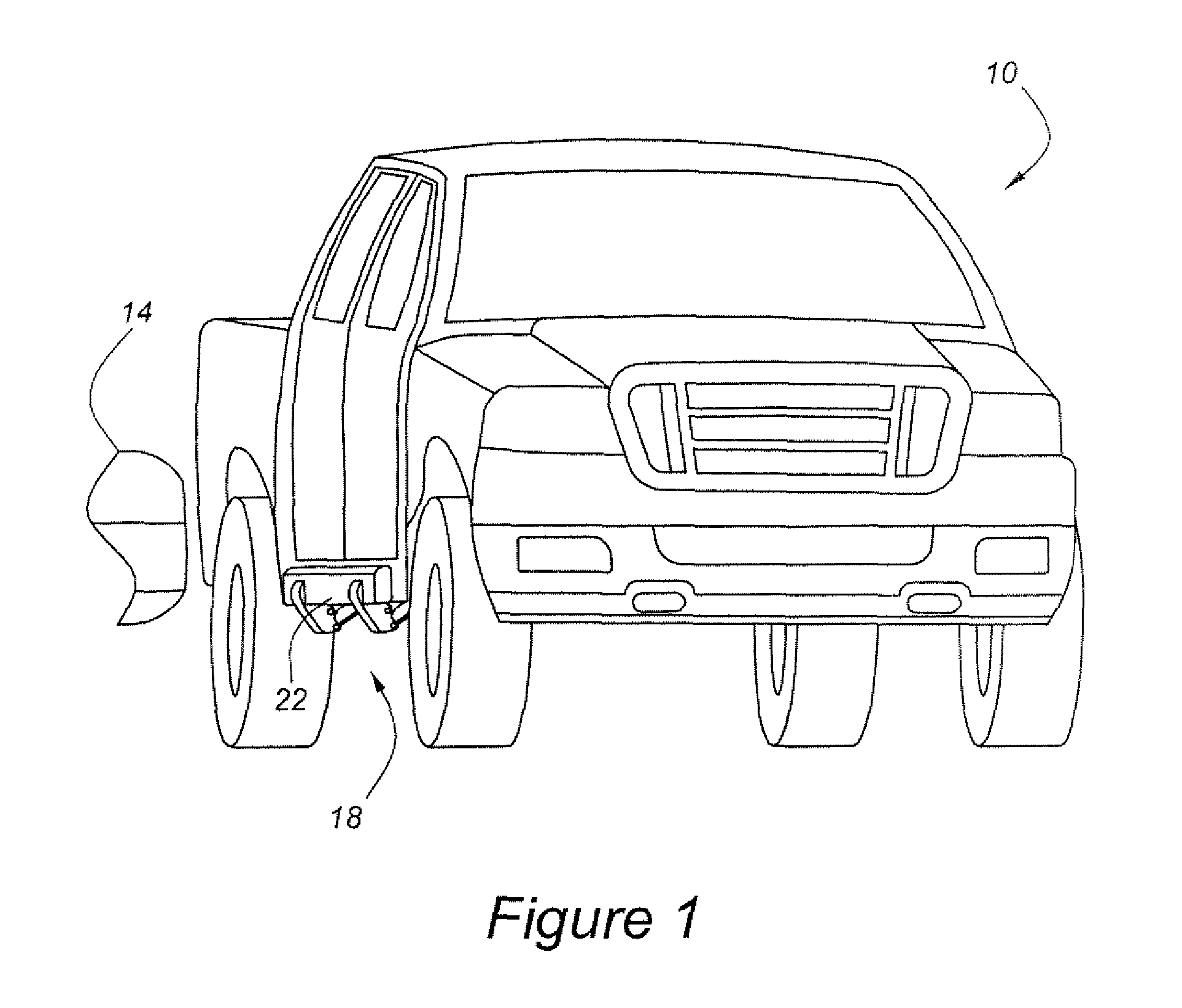
[0022] As shown in FIG. 1, vehicle 10 has a supplemental impact protection system, 18, with an external energy management structure including step beam 22, which has been rotated into a protective operating position. Beam 22 functions as an external energy management structure by resisting bending, buckling and twisting during impact events. FIG. 1 also shows bumper 14 of a striking vehicle which is moving into position to strike step beam 22, rather than the doors of vehicle 10.

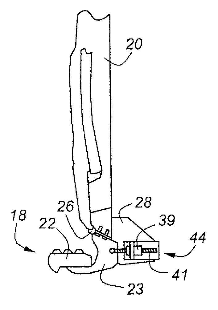
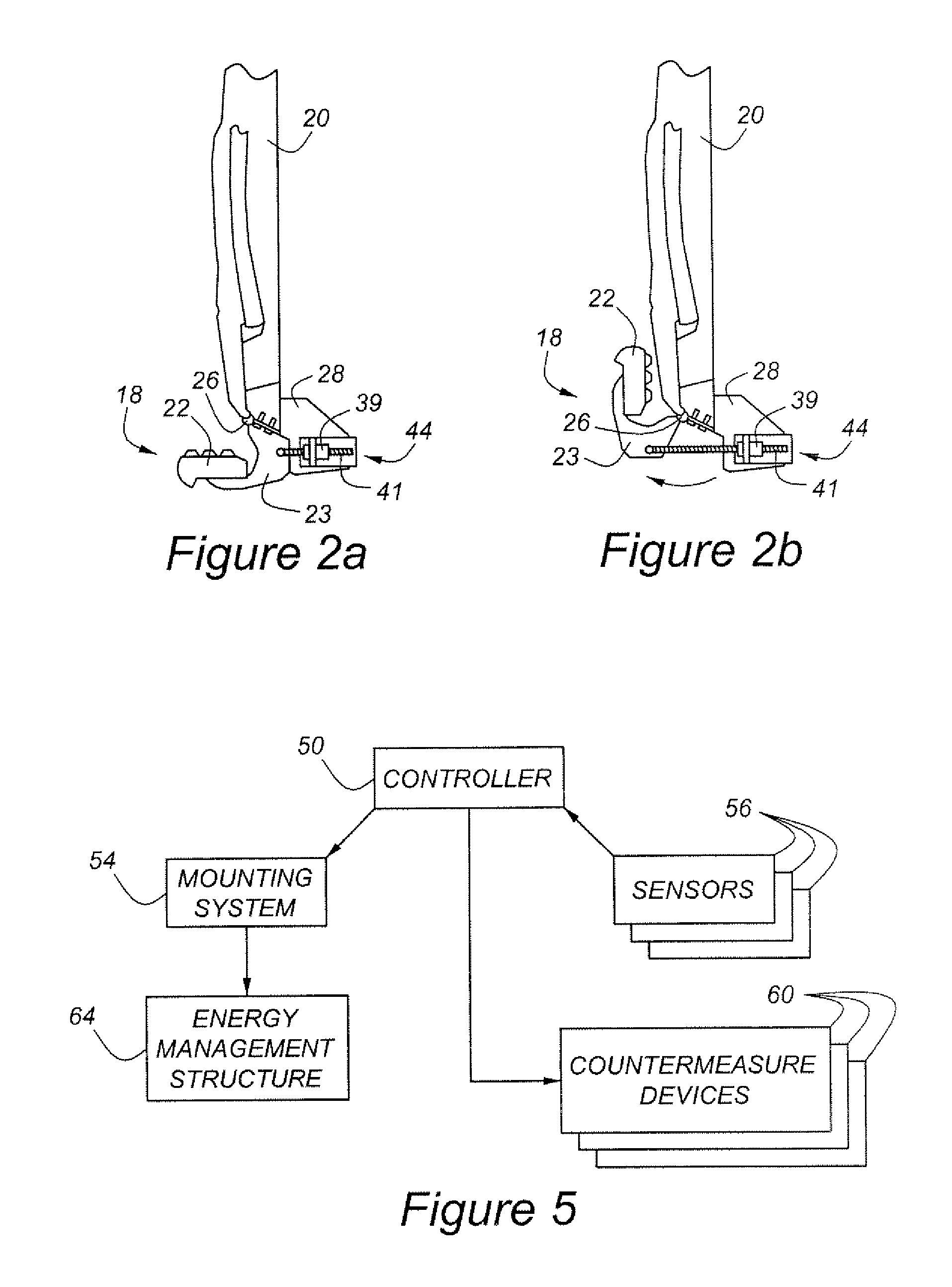
[0023] As shown in FIG. 2a, step beam 22 normally resides below door 20. Step beam 22 is mounted upon a plurality of body brackets, 23. Each body bracket 23 is rotatably mounted at a hinge point, 26, to body 28 of vehicle 10. Those skilled in the art will appreciate in view of this disclosure that body 28 may comprise either a unitized body, or a body or frame portion of a separate frame and body vehicle.

[0024] In FIG. 2b, step beam 22 is in its second, or deployed, position. This may also be termed an ele...


PUM


Abstract

A supplemental impact protection system for an automotive vehicle includes an external energy management structure having a first position for normal vehicle operation and a second position for deployment during an impact event. A mounting system allows selective positioning of the energy management structure in either the first or second position, as determined by a controller which assesses an impact potential of the vehicle and operates the mounting system to move the energy management structure to the second, or deployed, position in the event that the assessed impact potential satisfies a predetermined threshold.

Description

BACKGROUND OF THE INVENTION [0001] The present invention relates to a supplemental side impact protection system for an automotive vehicle. [0002] The presence of bumpers at the opposite ends of conventional passenger vehicles, coupled with the considerable crush space afforded by an engine compartment, generally located in the front of a vehicle, and a luggage compartment, generally located in the rear, have greatly facilitated the energy management required during impact events directed to the front and rear portions of conventional vehicles. At the sides of most vehicles, however, the crush distances are much less than those typically available for the front and rear of the vehicle. Moreover, the doors and rocker panels of most vehicles do not readily lend themselves to incorporation of the structures typically used for energy management in the front and rear bumpers of such vehicles. [0003] The present invention provides supplemental side impact protection by means of a deployab...

Claims


Application Information

Patent Timeline
Patent Type & Authority Applications(United States)
IPC IPC(8): B60R19/38
CPCB60R19/42B60R19/38
Inventor RYAN, SEANRUTHINOWSKI, RICHRAO, MANOHARPRASAD K.
Owner FORD GLOBAL TECH LLC
Learn More