Creating cuts in a transparent material using optical radiation

a transparent material and optical radiation technology, applied in laser surgery, eye surgery, etc., can solve the problems of inability to accurately focus the laser radiation, substantially prolong the creation of cuts, and reduce the number of paths, and reduce the geometry of the gas bubbles of adjacent sequential executions of the basic figur

Active Publication Date: 2017-09-21
CARL ZEISS MEDITEC AG
View PDF1 Cites 0 Cited by
  • Summary
  • Abstract
  • Description
  • Claims
  • Application Information

AI Technical Summary

Benefits of technology

[0029]The position of the laser impulses between two basic figures can thus be changed so that the spots of the one basic figure usually lie precisely in the gaps of the others. In this way, the geometric proximity of the gas bubbles of adjacent sequential executions of the basic figure is also reduced. It is also within the framework of the invention to transfer the basic figures into each other by simultaneously shifting, rotating, or stretching them by appropriately controlling the scanner in x direction and / or y direction in amplitude and phase position of the frequency components involved.
[0030]Example embodiments of the invention include that a rotation of the basic figure around its own axis is performed with a constant z-value so that there is a complete separation at this level (360° / number of the symmetry). For example, this level is located in the center of the lens. As the individual paths are spaced more closely in the center than at the edge of the lens, more spots are set in the center of the lens than at the edge in this process. Lenses, in which the center is harder as usual, can therefore be cut more easily using this approach.
[0031]It is also within the scope of the invention to reduce the number of paths to such an extent that a complete separation only takes place in the center and the level is just perforated in the edge region, so to speak. The number of selected paths must therefore only be so big that a simple removability of the lens during the subsequent distance of the lens of the eye is ensured. The number of paths is thereby preferably chosen depending on the hardness of the lens. This way, less paths can be chosen for soft lenses than for hard lenses. This facilitates that the time required for the respective level is short.

Problems solved by technology

The necessary precise focusing of the laser radiation is understandably impaired by the material through which the laser radiation is guided.
Otherwise, parts of the material in which material has already been cut, thus the cut has been already partially constructed, would disrupt the passage of the laser radiation and thus the desired precise focusing.
A further problem which occurs within the creation of cuts by guiding a focus along a path is the speed of the creation of cuts.
The deceleration, re-positioning or acceleration of the scanning device can substantially prolong the creation of cuts.
When used on the eye, not only is this onerous for a patient, as the surgical procedure lasts longer, the expenditure that must be met for precautions against unintended eye movements also increases with the increasing time required for the creation of cuts.
This problem is particularly great when a sectioning of transparent material is to be carried out, thus crossing cuts are required.
Because of the crossover points and the fact that the cuts must be constructed in layers contrary to the direction of incidence of the radiation, the deceleration, re-positioning and acceleration of the scanning device leads to a very great prolonging of the creation of cuts.
DE 102008027358 A1), these approaches are however limited to quite particular cut geometries.
When producing cuts in the cornea or the lens, the occurrence of gas bubbles is unavoidable.
The more complex the cutting patterns, the greater the risk that the gas bubbles have negative effects and could result in a capsule rupture, for example.
These curves result in a great progress, however still present disadvantages.
In the cuts guided from bottom to top on periodic paths, there is however furthermore the risk that gas bubbles result in negative effects due to the focused symmetrical cutting pattern.

Method used


Image

  • Creating cuts in a transparent material using optical radiation
  • Creating cuts in a transparent material using optical radiation
  • Creating cuts in a transparent material using optical radiation

Examples


Embodiment Construction

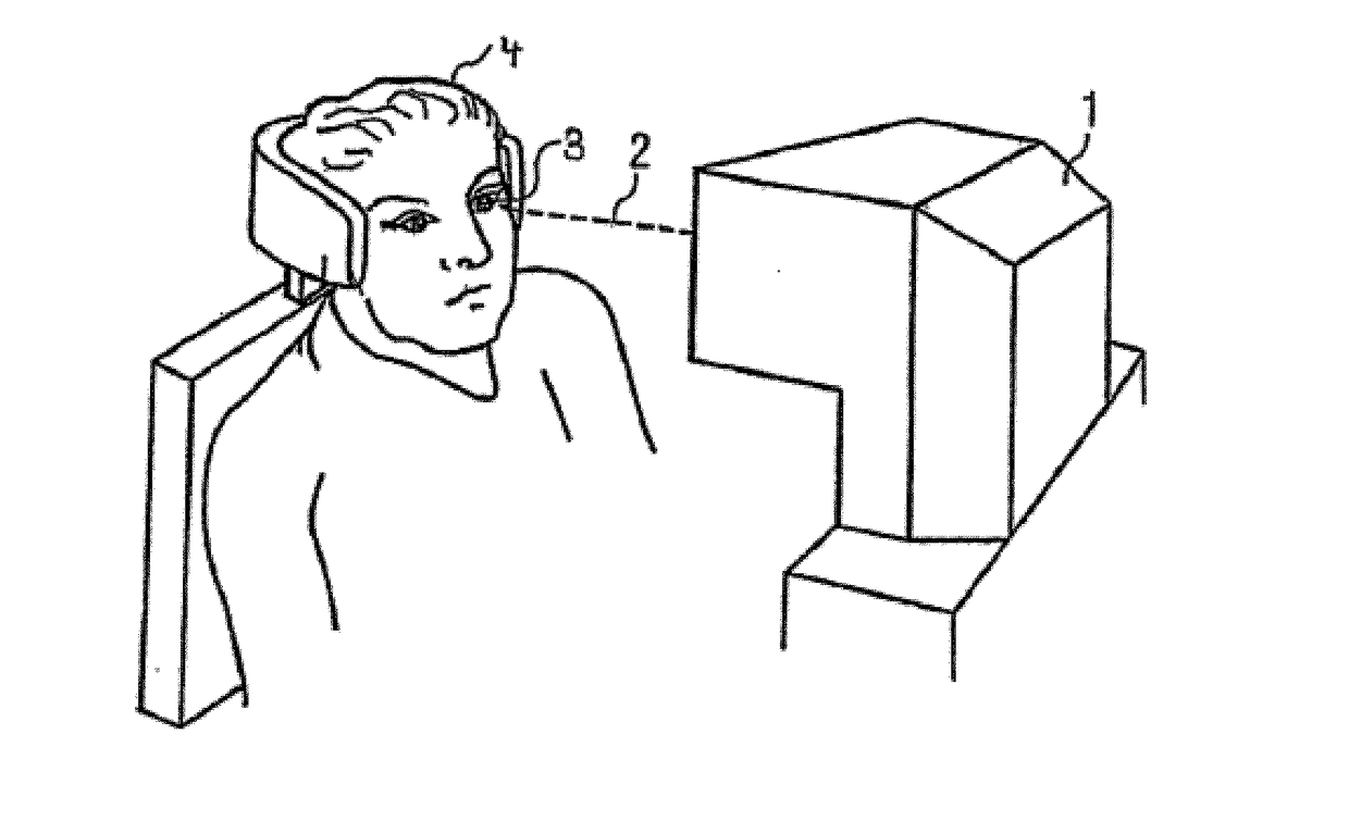
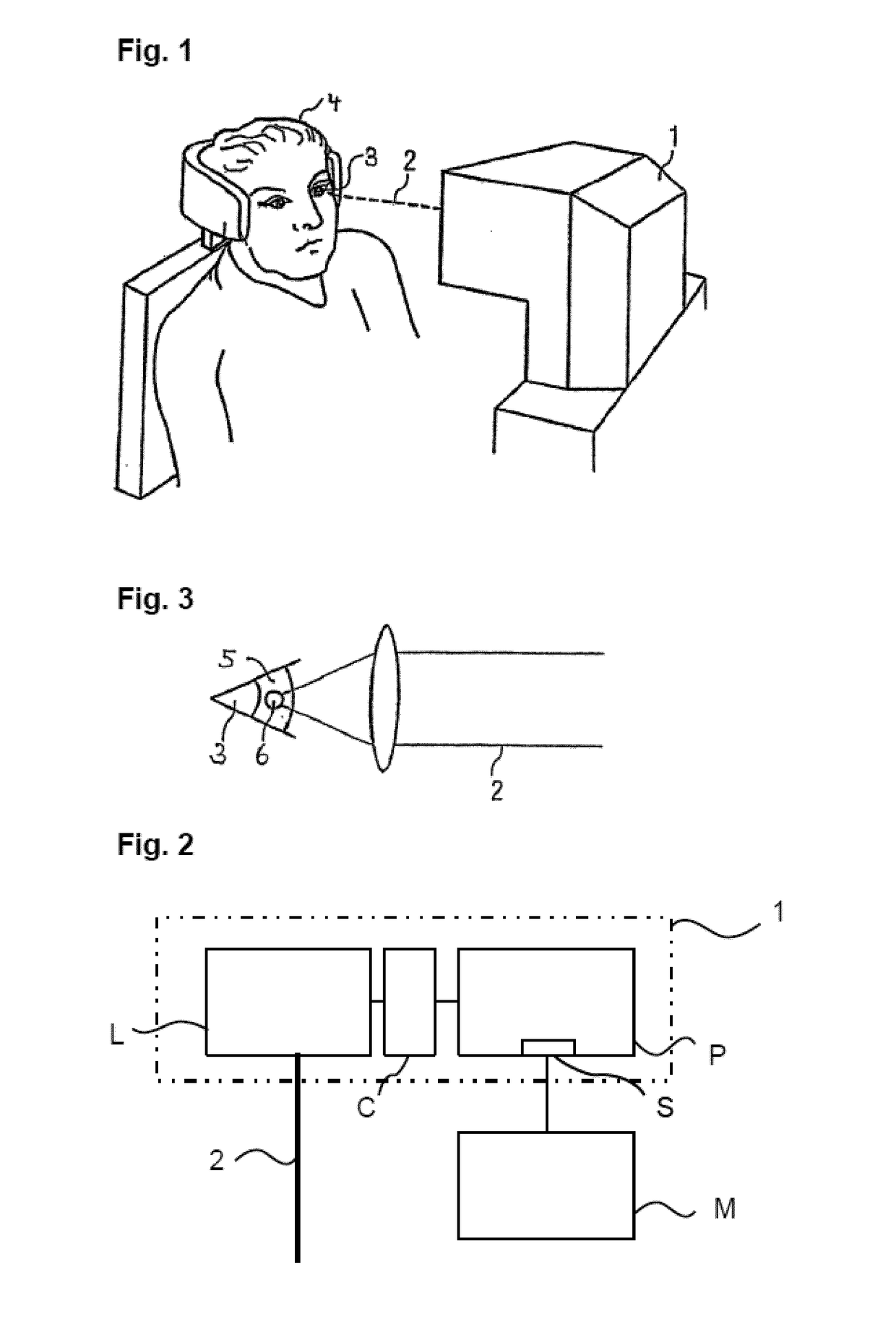
[0066]FIG. 1 depicts a treatment apparatus 1 for eye surgery. For example an eye-surgery process which is similar to that described in EP 1 159 986 A2 or U.S. Pat. No. 5,549,632 can be carried out with it. The treatment apparatus 1 creates a material cutting in transparent material using treatment laser radiation 2. This material cutting can be e.g. a creation of cuts, in particular the treatment apparatus for correcting defective vision can bring about a change on an eye 3 of a patient 4. The defective vision can include hyperopia, myopia, presbyopia, astigmatism, mixed astigmatism (astigmatism in which there is hyperopia in one direction and myopia in a direction at right angles thereto), aspheric errors and higher-order aberrations. The material cutting can, however, also be used in the field of ophthalmology on other tissues of the eye, e.g. for sectioning the crystalline lens in cataract surgery. Where reference is made to eye surgery below, this is to be understood in each cas...


PUM


Abstract

A method for creating cuts in a transparent material using optical radiation, the optical radiation being focused onto the material in a focal point and the focal point being shifted along a curve: A simple or double harmonic curve is used when seen at a right angle to a main direction of incidence of the radiation and preferably successively traveled curves do not lie on top of each other.

Description

RELATED APPLICATIONS[0001]This application is a National Phase entry of PCT Application No. PCT / EP2015 / 0724446 filed Sep. 29, 2015 which application claims the benefit of priority to German Application No. 10 2014 014 567.0, filed Sep. 29, 2014, and which claims the benefit of priority to German Application No. 10 2014 014 565.4, filed Sep. 29, 2014, the entire disclosures of which are incorporated herein by reference.FIELD OF THE INVENTION[0002]The invention relates to a method for creating cuts in a transparent material by application of optical radiation, wherein the optical radiation is focused on a focus in the material and the focus is shifted along a curved path.[0003]The invention furthermore relates to the method for producing control data for a laser device which sections a transparent material by focusing optical radiation, wherein the control data predetermine a curved path for a shift of a focus of the optical radiation in the material.[0004]Finally, the invention furth...

Claims


Application Information

Patent Timeline
Patent Type & Authority Applications(United States)
IPC IPC(8): A61F9/008
CPCA61F9/00825A61F2009/0087A61F2009/00897A61F2009/00887A61F2009/00872
Inventor KAHRA, STEFFENKUHNERT, HERRN JURGENBERGT, MICHAEL
Owner CARL ZEISS MEDITEC AG
Why Eureka
Try Eureka