
Detector for interferometric distance measurement

a technology of detection device and interferometer, which is applied in the direction of measurement device, interferometer, instruments, etc., can solve the problems of limited and achieve the goal of improving reliability, extending accuracy and/or reliability, and resolution and/or accuracy of polarization interferometer

Active Publication Date: 2007-10-04
MITUTOYO CORP
View PDF8 Cites 31 Cited by
  • Summary
  • Abstract
  • Description
  • Claims
  • Application Information

AI Technical Summary

Benefits of technology

[0004] As previously indicated, the resolution and / or accuracy of a polarization interferometer is often limited by the ability of the phase difference detector, also referred to simply as a detector herein, to generate one or more measurement signals which are truly related only to the phase difference between the object beam and reference beam outputs. The present invention is directed to a polarization interferometer phase difference detector which uses a novel configuration of components to advance the achievable phase difference measurement accuracy. It should be appreciated that phase difference measurement is already a refined art, and that even small improvements are valued for extending the accuracy and / or reliability of the most accurate measurement technology that is widely available (interferometry). The phase difference measurement is ultimately used to provide a measuring resolution and / or accuracy finer than the basic wavelength of radiation used in the interferometer. For this reason, the degree of meaningful measurement resolution supported by a detector is sometimes referred to as the “interpolation level”. Interpolation levels on the order of 1 / 100 of a wavelength are not uncommon. A detector according to this invention may provide meaningful interpolation well beyond this level, on the order of 1 / 1000 of a wavelength, and / or provide improved reliability, and reduced sensitivity to aging and environmental variables.
[0011] According to another aspect of the invention, the photodetector array may spatially filter the fringe pattern to provide 3-phase output signals that may undergo signal processing to remove certain errors when determining the spatial phase of the fringes.
[0017] In variations of this embodiment, a mixing polarizer may precede a non-polarizing beamsplitter along the optical path, or two separate mixing polarizers may be positioned after the beamsplitter and before the photodetector arrays along their respective optical paths. In another variation that is advantageous in terms of simplicity and optical signal strength, a polarizing beamsplitter may be used as the mixing polarizer, and no other polarizers are required in the dual-wavelength detector.

Problems solved by technology

As previously indicated, the resolution and / or accuracy of a polarization interferometer is often limited by the ability of the phase difference detector, also referred to simply as a detector herein, to generate one or more measurement signals which are truly related only to the phase difference between the object beam and reference beam outputs.
The diverging beams are input to a mixing polarizer, such that the beams exiting the mixing polarizer are similarly polarized and therefore interfere.

Method used


Image

  • Detector for interferometric distance measurement
  • Detector for interferometric distance measurement
  • Detector for interferometric distance measurement

Examples


Embodiment Construction

[0027] It should be understood that in various figures, illustrated component dimensions and spacings are selected for illustration clarity. Different parts of a figure may be drawn to different drawing scales, depending on various details to be emphasized. Such discrepancies should be apparent to one skilled in the art. Desirable and practical device configurations will be understood based upon the entirety of this disclosure.

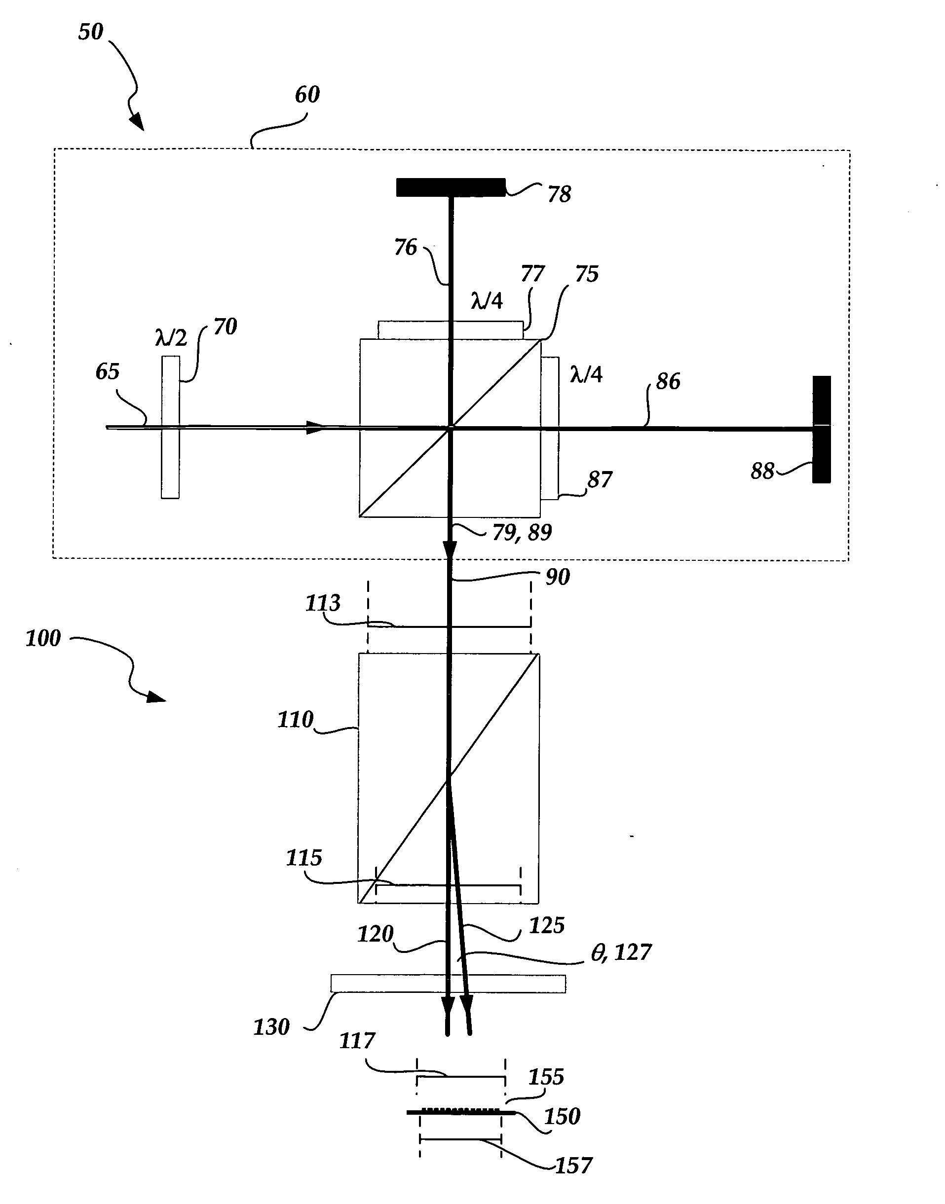
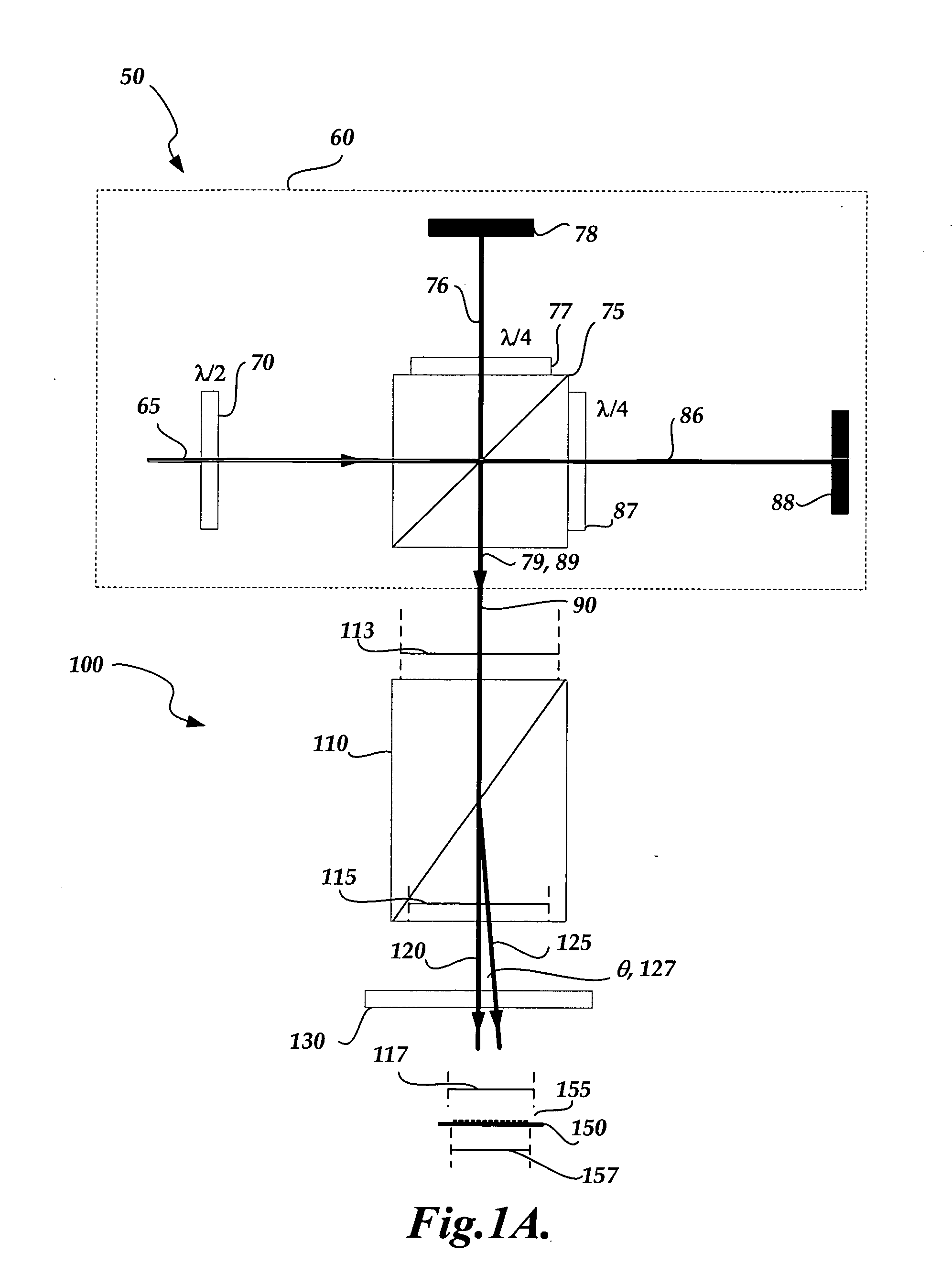
[0028]FIG. 1A shows an exemplary interferometric distance measuring apparatus 50, including an interferometer portion 60 and a detector 100. In the interferometer portion 60, a laser source (not shown) may be used to generate coherent radiation 65. The radiation 65 passes through a half-wave plate 70 and is then incident on a polarizing beam splitter 75, which transmits the portion of the radiation 65 that is “P” polarized to form reference beam 86, and reflects the portion of the radiation which is “S” polarized to form object beam 76. The reference beam 86 ...


PUM


Abstract

A detector for interferometric distance or displacement measurement. The detector may receive orthogonally polarized object and reference path output beams, which are directed to a polarization-sensitive beam deflecting element. The beam deflecting element deflects one or both orthogonally polarized beams to provide a desired divergence angle between the beams. The diverging beams are input to a mixing polarizer. The beams exiting the mixing polarizer are similarly polarized and therefore interfere. The interfering diverging beams form interference fringes. The spatial phase of the fringes relative to a photodetector array characterizes the phase difference between the object and reference beams of the interferometer.

Description

FIELD OF THE INVENTION [0001] This invention is directed to detectors for interferometric distance and displacement measuring devices. BACKGROUND OF THE INVENTION [0002] Laser interferometers are widely used to measure distances or displacements. One type, polarization interferometers, operate by projecting a coherent beam to a polarizing beamsplitter arranged to provide two coherent orthogonally polarized beams. One of the orthogonally polarized beams is projected along the fixed-length reference path of the interferometer and one along the distance-measuring object or sample path. The beams are directed through respective quarter wave plates, and reflected from the reference surface and the sample surface, respectively. The reflected beams return through the quarter wave plates and are recombined at the same polarizing beamsplitter, to form an output beam having two orthogonally polarized components. The desired distance or displacement measuring information is carried by the phas...

Claims


Application Information

Patent Timeline
Patent Type & Authority Applications(United States)
IPC IPC(8): G01B9/02
CPCG01B9/02G01B2290/70G01B9/02081G01B2290/45
Inventor SESKO, DAVID WILLIAM
Owner MITUTOYO CORP
Learn More