Reproducing circuit and a magnetic disk apparatus using same

Inactive Publication Date: 2007-10-04
HITACHI LTD
View PDF8 Cites 9 Cited by
  • Summary
  • Abstract
  • Description
  • Claims
  • Application Information

AI Technical Summary

Benefits of technology

[0004]The preamp used in the magnetic disk apparatus is composed of multiple operation modes such as a write mode for writing-in the data in a recording medium, a read mode for reading-out the data from the recording medium, and a sleep mode for stopping operation wherein switching between the operation modes is performed at a high speed. As a reproducing circuit, this invention includes the MR head bias voltage and switching operations besides those mentioned above. With higher density of recording media, higher density of MR head media and higher transfer speed of the apparatus, it is requested for the preamp to have a shorter transition time among the various operation modes. Also, in response to the fact that the breakdown resistance decreased in spite of achievement of higher sensitivity of the head medium in the reproducing circuit, it is important to further pay attention to overvoltage of the MR head bias voltage which easily occurs when switching operation modes. As measures, for example, both prevention of overvoltage of the MR head bias voltage and higher speed switchi

Problems solved by technology

However, a reduction in breakdown resistance of the MR head increases the possibility of inducing deterioration of ch

Method used


Image

  • Reproducing circuit and a magnetic disk apparatus using same
  • Reproducing circuit and a magnetic disk apparatus using same
  • Reproducing circuit and a magnetic disk apparatus using same

Examples


Example

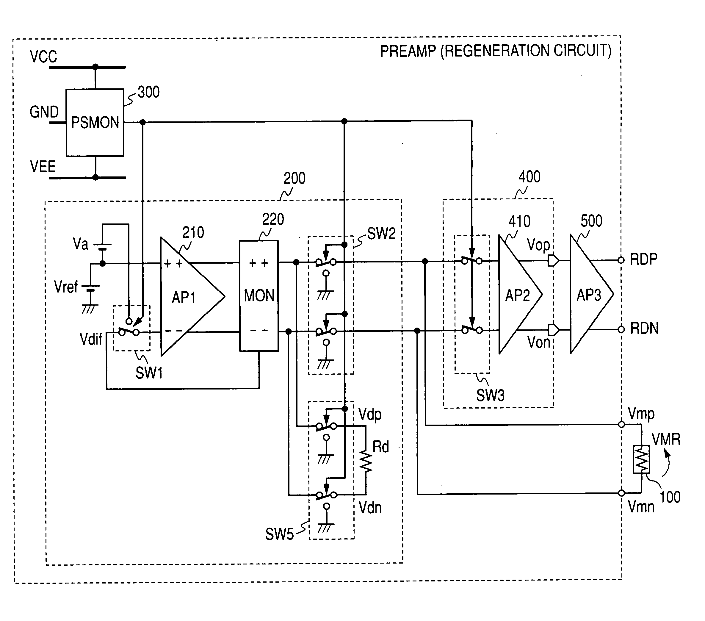
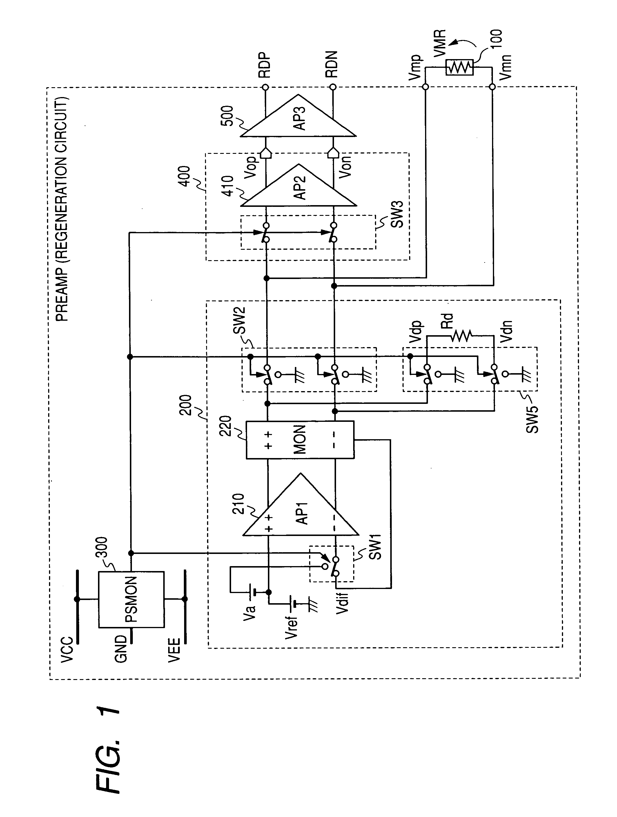
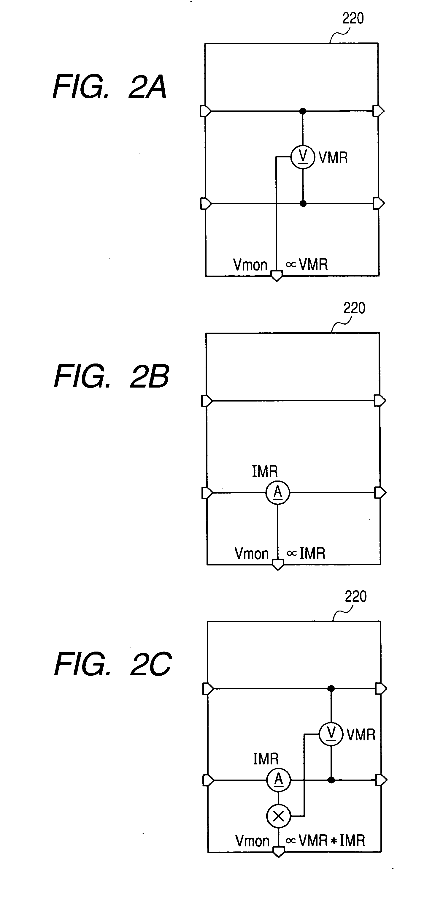
[0033]FIG. 1 shows a first embodiment of a reproducing circuit for magnetic disk apparatus wherein this invention is applied. This reproducing circuit is composed of a MR head 100, a bias circuit 200 which provide a bias voltage VMR specified in the ME head by Vref, a power supply voltage monitor circuit 300 for monitoring the power supply voltage variances, and an initial-stage amplifier 400 and a later-stage amplifier 500 that amplify output signals of the MR head. The bias circuit 200, after an amplifier 210 compares the output voltage Vdif of the monitor circuit 220 which monitors the bias status of the MR head 100, with the Vref, controls to the bias voltage VMR specified by the Vref. The monitor circuit 220 monitors one of (a) bias voltage VMR of the MR head 100, (b) bias current IMR running through the MR head 100, and (c) the power generated in the MR head 100 to output a voltage Vdif as shown in FIG. 2 based on the objective of the control of the MR head 100 so that the bia...

Example

[0034]FIG. 3 shows a second embodiment of the reproducing circuit for magnetic disk apparatus wherein this invention is applied. This reproducing circuit is composed of a MR head 100, a bias circuit 200 that provides a bias voltage VMR specified based on the Vref in the MR head, a bias circuit 300 generating a current that depends upon the power supply voltage, an initial stage amplifier 400 and a later stage amplifier (now shown) that amplify the output signals of the MR head.

[0035]Regarding the control of bias voltage VMR, the constitution and operation are common to those shown in FIG. 14 and FIG. 15 so that their explanations are omitted and only the differences will be explained below.

[0036]The source followers for transistors MP3 and NM3 have resistances Roff that are connected respectively between the output source terminal and the ground to configure analog switches SF1 and SF2 that are controlled by the power supply voltage dependent current supplies CS1 and CS2. Also, the ...

Example

[0038]FIG. 16 shows a third embodiment of the reproducing circuit for magnetic disk apparatus wherein the present invention is applied. The circuit configuration is similar to that in the second embodiment in FIG. 3, but the point of difference is that the power supply voltage dependent current CS3 is supplied to the monitor circuit 210. FIG. 7 shows a circuit diagram of the monitor circuit 210. Since FIG. 7 has common configuration and operations as those in the circuit shown in FIG. 15, explanations will be omitted and only the points of difference will be explained.

[0039]In the second embodiment, since the bias voltage VMR is blocked by the effect of this invention when the power supply voltage decreases as shown in FIG. 5, the output voltage Vdif of the monitor circuit 210 becomes a power supply VCC. Thus, the amplifier 220 in FIG. 3 controls to increase voltage (V1-V2) between the gates of transistors MP3 and MN3 in order to provide the bias voltage VMR a specified value. Since...


PUM


Abstract

A reproducing circuit for magnetic disks wherein a MR head bias voltage does not exceed the specified value during any malfunction of the power supply voltage including the cases of power supply ON/OFF, and the central voltage of the MR head is controlled to the ground. The reproducing circuit for magnetic disk apparatus is composed of a MR head, a bias circuit that provides bias voltage specified relative to the MR head, an amplifying circuit for amplifying the output signals of the MR head, a power supply voltage monitor circuit that monitors the changes in the power supply voltage, and a control circuit that is controlled by the power supply voltage monitor circuit. MR bias voltage does not exceed the specified value during any malfunction of the power supply voltage including the cases of power supply ON/OFF, and the central voltage of the MR head is controlled to the ground such that the MR head is protected.

Description

CLAIM OF PRIORITY[0001]The present application claims priority from Japanese application JP 2006-092778 filed on Mar. 30, 2006, the content of which is hereby incorporated by reference into this application.FIELD OF THE INVENTION[0002]This invention relates to a reproducing circuit and a magnetic disk apparatus using the reproducing circuit. In particular, it relates to a reproducing circuit when it is effectively used in magnetic disk apparatus using a magnetoresistive head (hereinafter referred to as MR head).BACKGROUND OF THE INVENTION[0003]Japanese Patent JP-A No. 2002-358604 is a reference describing a current bias circuit of the magnetic signal detecting head that is used in the magnetic recording apparatus. FIG. 1 of the same reference shows an example of a circuit for preventing a large current from running temporarily into the MR head when switching the head or when switching the bias current.SUMMARY OF THE INVENTION[0004]The preamp used in the magnetic disk apparatus is co...

Claims


Application Information

Patent Timeline
IPC IPC(8): G11B5/03
CPCG11B2005/0016G11B5/40
Inventor SHINOMIYA, TOSHIOKOBAYASHI, YOICHIRONOMURA, YUKI
Owner HITACHI LTD
Why Eureka
Try Eureka