Wireless communication apparatus

a communication apparatus and wireless technology, applied in the field of wireless communication apparatus, can solve the problems insufficient performance enhancement techniques, and the current available technology for ad hoc network architecture involves a number of unsolved technical problems, and achieve the effect of improving communication quality and simplifying communication

Inactive Publication Date: 2007-10-04
KOKUSA ELECTRIC CO LTD
View PDF2 Cites 13 Cited by
  • Summary
  • Abstract
  • Description
  • Claims
  • Application Information

AI Technical Summary

Benefits of technology

[0007]The present invention by provides a wireless communication apparatus for use in a network, to simplify and improve the quality of communication to solve the problem noted above.

Problems solved by technology

Therefore, it is not an adequate technique for enhancing the performance of packet transmission processing in a system in which user terminals are connected wirelessly and the network topology constantly varies (ad hoc network).
However, the currently available technology for ad hoc network architecture involves a number of unsolved technical problems.
Since terminals constituting an ad hoc network perform wireless communication, their linking is less stable than in a wired network.
Here, a problem is posed of how to dynamically detect an efficient and stable route in such an environment.

Method used


Image

  • Wireless communication apparatus
  • Wireless communication apparatus
  • Wireless communication apparatus

Examples


embodiment 1

[0085]Embodiment 1 will be newly described below with reference to FIG. 15 through FIG. 20. FIG. 15 is a functional block diagram of a node. FIG. 16 is a hardware block diagram of the node. FIG. 17 and FIG. 18 illustrate the link establishment table of node A. FIG. 19 is a flowchart of processing of packet discarding. FIG. 20 illustrates the transmission queue of node A after the processing of packet discarding.

[0086]Referring to FIG. 15, a node 100 is configured of a wireless unit 1 including a wireless antenna 110 and a wireless signal transceiver 90, a packet transmission queue 60 which is a FIFO memory connected to the wireless unit 1, a packet transmission control unit 9 and an intra-queue packet control unit 2 connected to the packet transmission queue 60, a route information assigning unit 3 connected to the packet transmission queue 60, a route information storage unit 8 connected to the route information assigning unit 3 and the intra-queue packet control unit 2, a route in...

embodiment 2

[0096]Embodiment 2 will now be newly described with reference to FIG. 21 and FIG. 22. FIG. 21 here is a flowchart of rerouting, and FIG. 22 illustrates the transmission queue of node A after the rerouting.

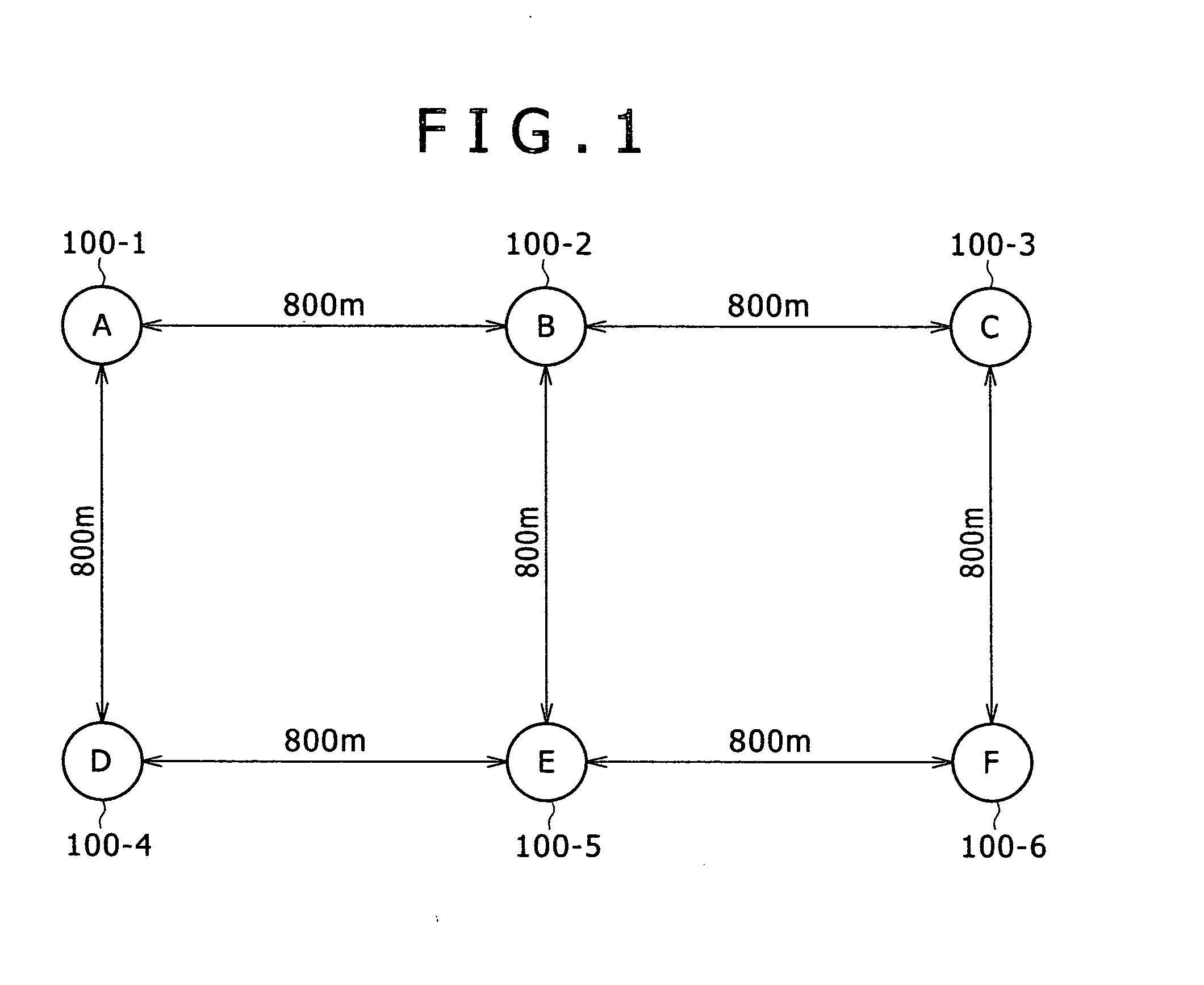
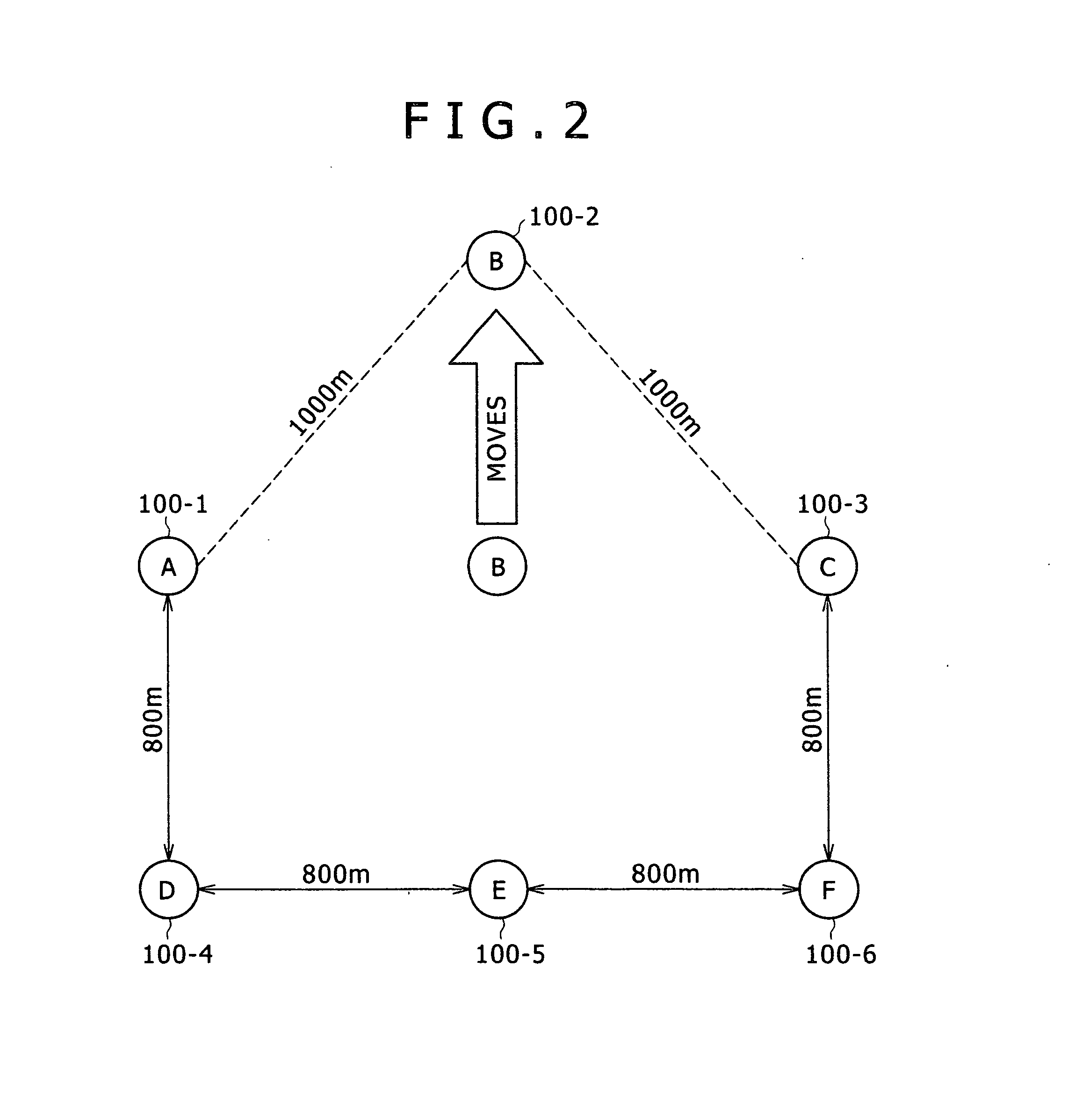
[0097]When the network topology changes from the state of FIG. 1 to that of FIG. 3 via that of FIG. 2, the routing table of node A is switched over from that of FIG. 9 to that of FIG. 11. In Embodiment 2, the routing layer confirms the transmission queue at the ting of this switch-over of the routing table, and the queued data is rerouted.

[0098]Referring to FIG. 21, first the queue pointer is initialized (S21). Next, it is determined whether or not the queue pointer is longer than the queue length (S22), and if NO, the processing is ended. If YES at step 22, it is determined whether or not the forwarding IP address of Qdata is present in the routing table (S23). If YES at step 23, in order to check whether or not the data awaiting transmission within the transmission queue is consi...

embodiment 3

[0102]A case is supposed here in which a data transfer from node A to node C and a data transfer from node A to node D are taking place at the same transmission rate within the same period in a state in which the network topology is configured as shown in FIG. 1 and each node has its link established. Then the link establishment table of node A is as shown in FIG. 17.

[0103]When the network topology changes from the state of FIG. 1 to that of FIG. 3 via that of FIG. 2, node A will recognize link severance from node B. The link establishment table of node A after the link severance will be like FIG. 18, wherein node B is deleted. In this embodiment, at the timing of recognizing this link severance, the routing layer recognizes the transmission queue and replaces the forwarding MAC address of data which need not be transmitted with the MAC address of a link-established node. Details of the operations from the recognition of this link severance to the replacement of the forwarding MAC a...


PUM


Abstract

The number of wasteful attempts at wireless data transmission to any wireless terminal with which communication is impossible is to be reduced. The wireless terminal constantly monitors the state of communication between wireless terminals and, when any change in the state of communication is found, one set or plural sets of data awaiting wireless transmission are checked to see whether or not they are destined for any wireless terminal with which communication is possible, the data being discarded if wireless communication is determined to be impossible. The number of wasteful attempts at wireless data transmission can be thereby reduced.

Description

CLAIM OF PRIORITY [0001]The present application claims priority from Japanese patent application serial no. 2006-087803, filed on Mar. 28, 2006, the content of which is hereby incorporated by reference into this application.BACKGROUND OF THE INVENTION [0002]The present invention relates to a wireless communication apparatus, and mote particularly to a wireless communication apparatus which can be suitably applied to a wireless communication network whose topology varies.[0003]Japanese Patent Application Laid-Open No. 6-152650 discloses a communication apparatus which regularly monitors the transmission buffer of a packet transmission device, discards the packets which it holds from within the transmission buffer.[0004]However, the technique disclosed by Japanese Patent Application Laid-Open No. 6-152650 is intended to prevent the capacity to process packet transmission from deterioration by discarding packets attributable to erroneous operation of the packet transmission device. The...

Claims


Application Information

Patent Timeline
Patent Type & Authority Applications(United States)
IPC IPC(8): H04J3/08H04L45/24H04L47/32H04W40/34H04W8/00H04W40/30H04W40/38H04W84/18
CPCH04J3/1617H04W40/38H04W40/30H04W8/005
Inventor TAKATANI, YUKIHIROISHIZAKI, MASAYUKI
Owner KOKUSA ELECTRIC CO LTD
Why Eureka
Try Eureka