Pod cramping unit, load port equipped with pod cramping unit and mini-environment system including pod and load port

a technology for cramping units and load ports, which is applied in the direction of pile separation, transportation and packaging, packaging goods types, etc., can solve the problems of increasing the weight of the pod, increasing the size, and increasing the load generated by inertia upon moving the pod, so as to achieve the effect of reliably keeping the pod fixed

Active Publication Date: 2007-10-04
TDK CORPARATION
View PDF10 Cites 3 Cited by
  • Summary
  • Abstract
  • Description
  • Claims
  • Application Information

AI Technical Summary

Benefits of technology

[0013] The present invention has been made in view of the above described situations and has as an object to provide a pod cramping unit that can reliably keep a pod fixed on a support table even if a load is applied inadvertently on the pod, a load port having such a pod cramping unit and a mini-environment system including such a unit and a load port.

Problems solved by technology

Furthermore, with an increase in the weight of the pod accompanied by an increase in the size thereof, a load generated by inertia upon moving the pod and an impact force that may be caused upon transferring a wafer also becomes larger.
In such cases, the fastening ability of conventional cramp units is relatively low, and the position of the pod may be displaced and the pod may be dislocated by a load that acts on the pod upon movement of the pod or other occasions.
Therefore, it is difficult to keep the pod in the fixed state.
Accordingly, they do not function effectively in keeping the pod fixed.

Method used


Image

  • Pod cramping unit, load port equipped with pod cramping unit and mini-environment system including pod and load port
  • Pod cramping unit, load port equipped with pod cramping unit and mini-environment system including pod and load port
  • Pod cramping unit, load port equipped with pod cramping unit and mini-environment system including pod and load port

Examples


first embodiment

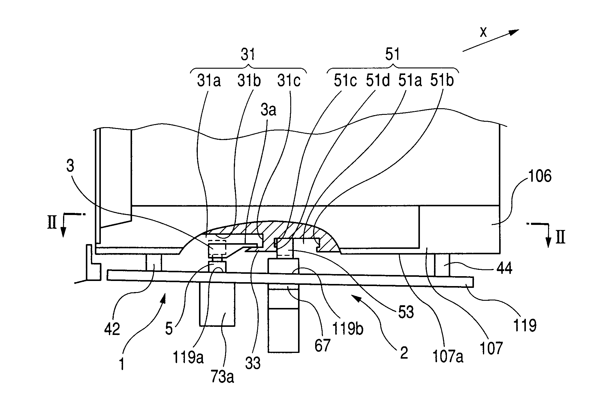
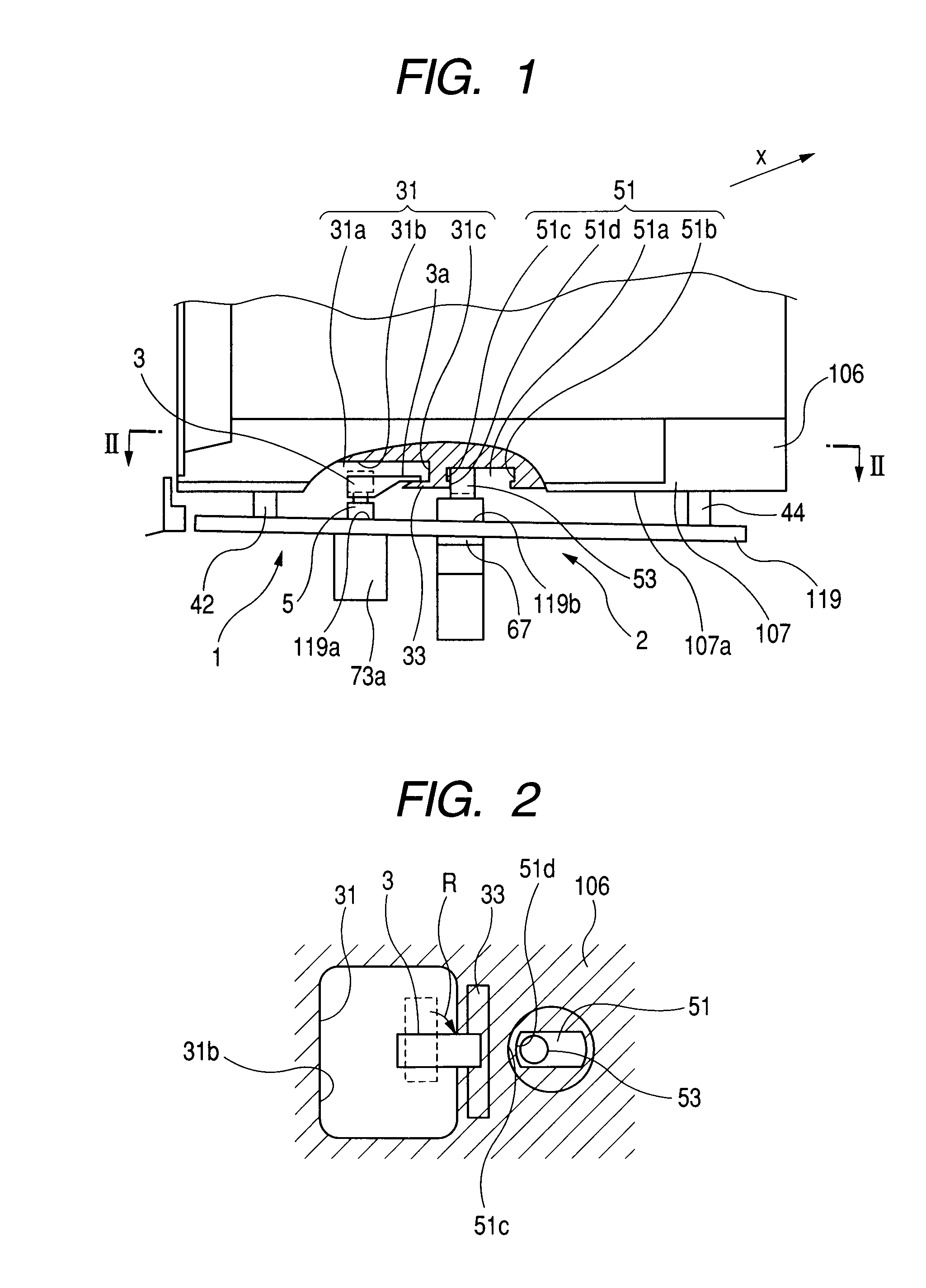
[0028] A first embodiment of the pod cramping unit according to the present invention will be described in the following with reference to the drawings. FIG. 1 schematically shows a cramping mechanism having a pod cramping unit according to an embodiment of the present invention. FIG. 2 is a cross sectional view taken along line II-II in FIG. 1. FIG. 2 shows a part of the pod body, as seen from the bottom plate side thereof, in the state in which the cramping unit is in engagement with the engagement portion of the pod.

[0029] The cramping mechanism includes a first engagement portion 31 and a second engagement portion 51 provided on the bottom plate 107 of the pod body 106, and a pod cramping unit provided on an FIMS system (i.e. a load port) 140. The pod cramping unit has a cramping unit 1 and a restricting unit 2. The first engagement portion 31 is an element that restricts movement of the pod with respect to the vertically upward direction (i.e. the upward direction in FIG. 1 or...

second embodiment

[0052] While in the first embodiment the restriction pin is inserted in the engagement recess for center retaining, in the second embodiment holes for forklift pin are used to restrict lateral movement of the pod body 106.

[0053]FIG. 5 is a partial view schematically showing a part of a cramping mechanism having a cramping unit according to the second embodiment. FIG. 6 is a cross sectional view taken along line VI-VI in FIG. 5 and shows the cramping mechanism in operation as seen from the bottom plate side of the pod body. The cramp portion and the first engagement portion in the second embodiment are the same as those in the first embodiment. In the following, only the restriction unit and the second engagement portion will be described.

[0054] In compliance with a SEMI standard, positioning holes serving as holes 251b for receiving forklift pin are provided on the edge of the bottom plate 207 of the pod body 206. When the pod is transported, forklift pins provided on a forklift u...

third embodiment

[0062] In the following, an FIMS system having the above described cramp mechanism, a pod to be placed thereon and a wafer transferring apparatus on which the FISM system is mounted will be described as an embodiment of the present invention with reference to FIGS. 7 and 8. FIG. 7 schematically shows a system for transferring wafers or the like from a pod to a processing apparatus. FIG. 8 is a partly sectional illustration of a support table, an aperture, a door and related structures in the FIMS system.

[0063] The system illustrated in FIG. 7 includes a small space 105 kept in a highly clean state, a wafer transfer robot 114 set at the center thereof, a substrate receiving stage 131 of the processing apparatus (not shown) provided on a first wall of the space 105 and an FIMS system 140 provided on a second wall of the space 105.

[0064] The FIMS system 140 includes the aforementioned second wall of the small space 105, an opening102, a pod opener or door 103 and a support table 119....


PUM


Abstract

The invention is directed to a pod cramping unit for fixing a pod to a support table in a load port, the pod including a pod body capable of storing a wafer in the interior thereof and having an opening through which the wafer is to be taken out of/brought into the interior and a lid attached to the pod body to close/open the opening, the load port having a pod opener that opens/closes the lid to allow to bring the wafer out of/into the interior of the pod. The pod cramping unit includes a cramp portion that is provided on the support table and adapted to engage with a first engagement portion provided on a lower surface of the pod body to restrict upward movement of the pod relative to the support table, a restriction pin that is movable upwardly and downwardly relative to the support table and adapted to engage with a second engagement portion provided on the lower surface of the pod body to restrict movement of the pod in a disengaging direction that causes disengagement between the first engagement portion and the cramp portion, and a vertically driving portion that moves the restriction pin up to/down from the second engagement portion.

Description

BACKGROUND OF THE INVENTION [0001] 1. Field of the Invention [0002] The present invention relates to what is called an FIMS system (front-opening interface mechanical standard system) (or load port) that is used in semiconductor manufacturing process, upon transferring a wafer(s) stored in a transport container called a pod into a semiconductor processing apparatus, as a structure on which the pod is placed. More particularly, the present invention relates to components related to an FIMS system on which a pod (one referred to as an FOUP (front-opening unified pod)) is placed and that transfers a semiconductor wafer(s) from the pod, namely a pod cramping unit for fixing a pod on the FIMS system, a load port on which a pod compatible with that cramping unit is to be placed, and a mini-environment system including a pod and a load port that are compatible with that cramping unit. [0003] 2. Related Background Art [0004] In the past, the semiconductor manufacturing process had been perf...

Claims


Application Information

Patent Timeline
Patent Type & Authority Applications(United States)
IPC IPC(8): B65H1/00
CPCH01L21/67379H01L21/67775H01L21/67772Y10S414/14H01L21/6773
Inventor MIYAJIMA, TOSHIHIKOEMOTO, JUNHORIBE, HIDETOSHI
Owner TDK CORPARATION
Why Eureka
Try Eureka