
Two-way generation tidal power plant with one-way turbines

a technology of tidal power plants and turbines, which is applied in the direction of machines/engines, renewable energy generation, greenhouse gas reduction, etc., can solve the problems of increasing equipment costs, reducing the overall efficiency of the plant, and less reliable two-way runners, so as to achieve the same overall efficiency, less expensive, and reliable

Inactive Publication Date: 2007-10-04
GOKHMAN ALEXANDER
View PDF3 Cites 15 Cited by
  • Summary
  • Abstract
  • Description
  • Claims
  • Application Information

AI Technical Summary

Benefits of technology

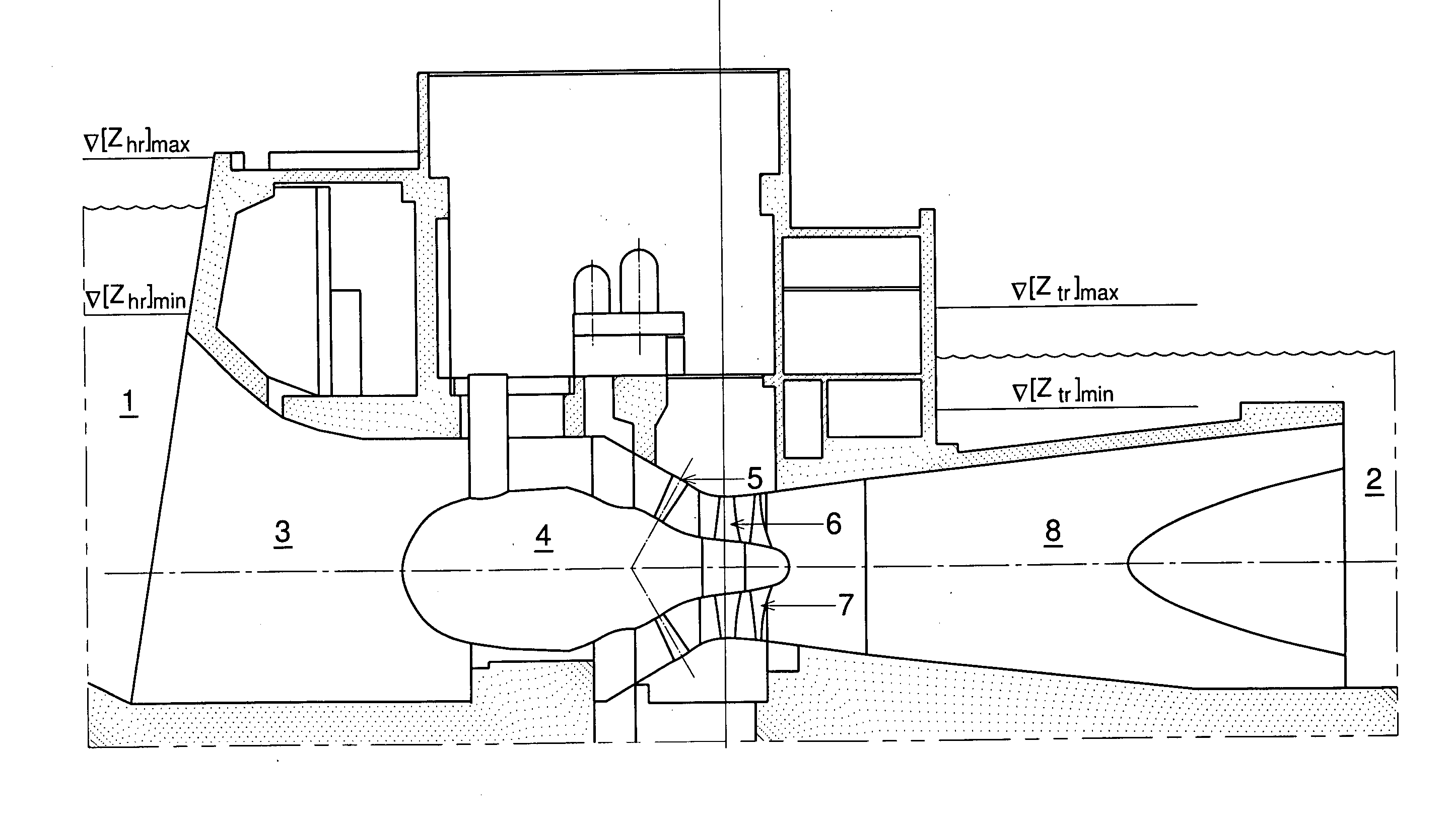
[0017] The power house is the same as in a conventional low head hydro power plant and can be fitted with conventional bulb turbines with the electrical generator located in the bulb. The turbine runner could be a Kaplan runner or an axial propeller. An ideal turbine for such a power house would be a bulb turbine with an axial propeller and an exit stay apparatus (see Hydraulic Trbine and Exit Stay Apparatus therefor, U.S. Pat. No. 6,918,744 B2, Jul. 19, 2005). A bulb turbine with an axial propeller and an exit stay apparatus has almost the same overall efficiency as a bulb turbine with a Kaplan runner, but is more reliable, less expensive, and fish friendly.
[0018] A two-way generation tidal power plant with one-way turbines and with head and tail reservoirs is the most advantageous economically in the case of a tidal power plant with a barrage much longer than the power house. In this case the construction of two additional barrages forming the reservoirs will increase the cost of the plant construction much less than by a factor of two compared to a one-way generation plant, whereas the yearly energy production will increase two-fold and the time to recoup the capital will substantially decrease. The proposed tidal power plant for Fundy bay is the best application for a two-way generation tidal power plant with one-way turbines and with head and tail reservoirs, since its total length from shore to shore is 7.91 km and the power house length (along the barrage) is only 2.34 km.

Problems solved by technology

This makes two-way runners more expensive and less reliable.
However, due to mechanical problems they allow only ebb generation.
The use of converters decreases the overall efficiency of the plant and increases the cost of equipment.

Method used


Image

  • Two-way generation tidal power plant with one-way turbines
  • Two-way generation tidal power plant with one-way turbines
  • Two-way generation tidal power plant with one-way turbines

Examples


Embodiment Construction

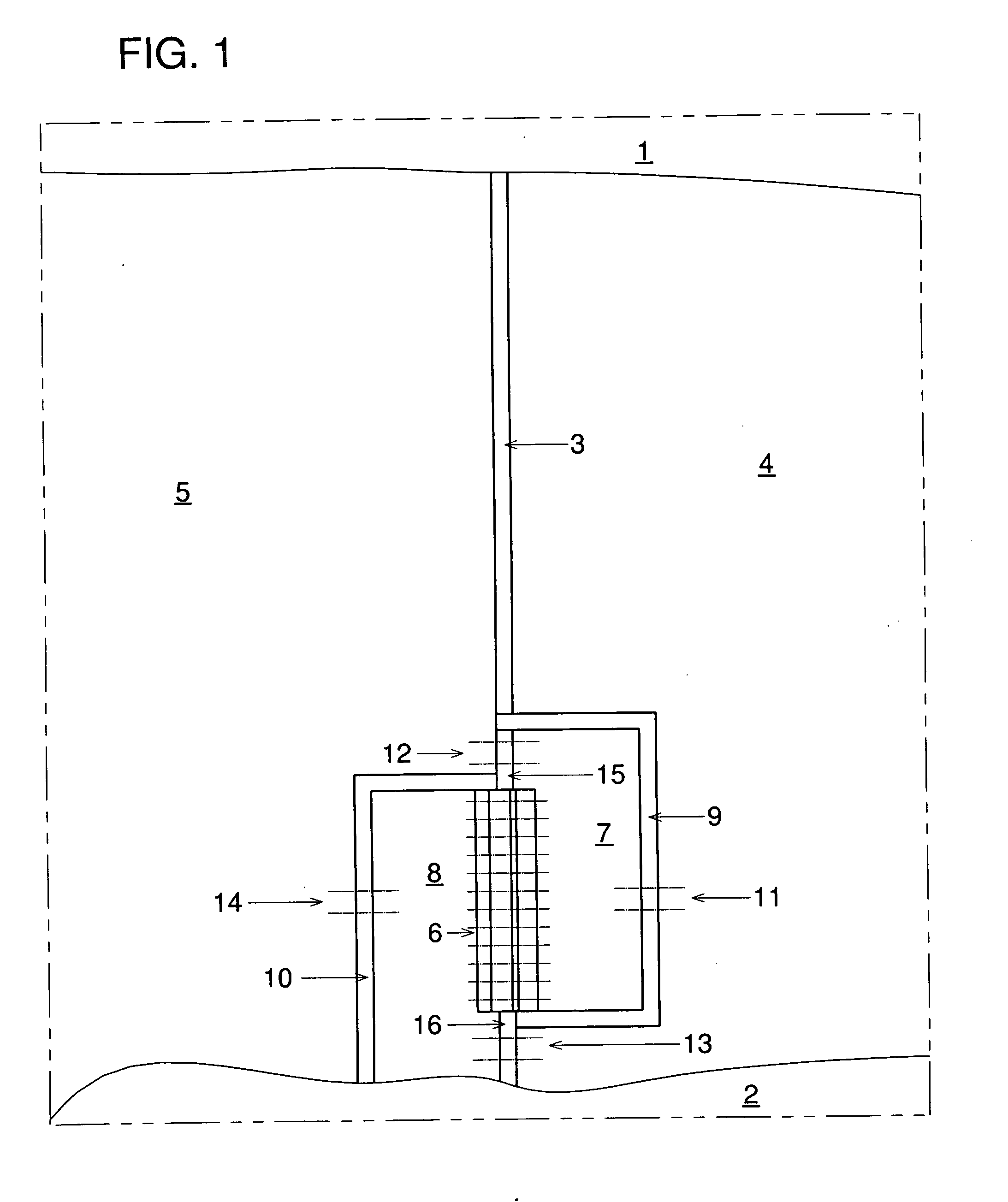
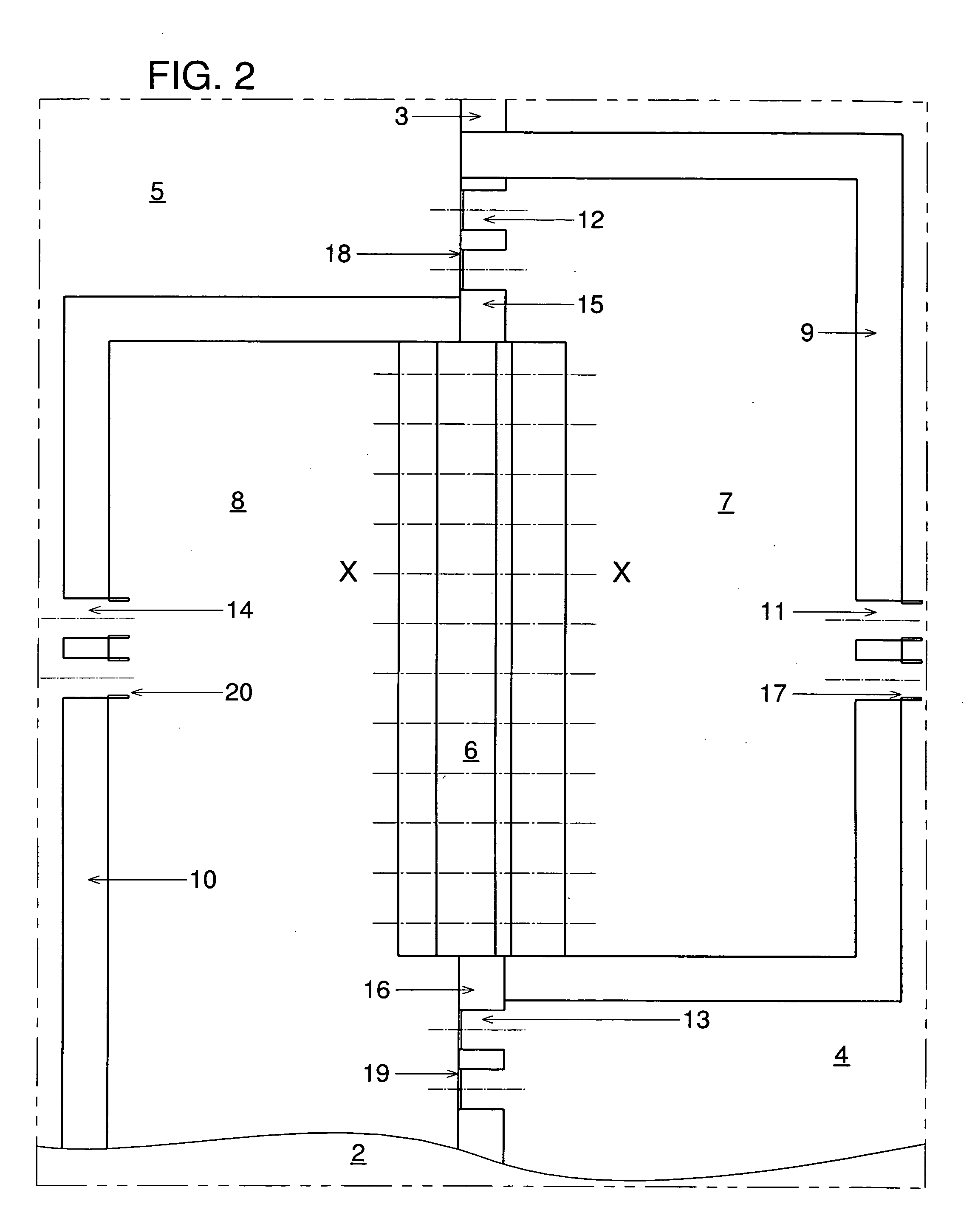
[0023] Referring now to FIG. 1, a two-way generation tidal power plant with one-way turbines having a main barrage and two additional barrages forming the head reservoir in the outer bay and the tail reservoirs in the basin is shown. The tidal power plant comprises a main barrage 3 and a power house 6 between bay shores 1 and 2. A power house 6 is located at the shore 2. A head reservoir 8 is formed by a head barrage 10 located in the outer bay 5, a power house 6, a part of a main barrage 16 located between a power house 6 and the shore 2, and the shore 2 between a head barrage 10 and a part of a main barrage 16. A tail reservoir 7 is formed by a tail barrage 9 located in the basin 4, a power house 6, and a part of a main barrage 15 located between a power house 6 and a tail barrage 9. There are sluices 14 connecting a head reservoir 8 with the the outer bay 5 and sluices 13 connecting a head reservoir 8 with the basin 4. There are also sluices 12 connecting a tail reservoir 7 with ...


PUM


Abstract

The invention is a two-way generation tidal power plant with one-way turbines. The purpose of the invention is to have a two-way generation tidal power plant with the same high efficiency for both ebb and flood generations. In order to achieve this, additional head and tail reservoirs for a power house are formed by additional barrages in the basin and the outer bay. During flood generation the head reservoir is connected to the outer bay and the tail reservoir is connected to the basin. During ebb generation, the head reservoir is connected to the basin and the tail reservoir is connected to the outer bay.

Description

BACKGROUND OF THE INVENTION [0001] This invention relates to tidal power plants. More specifically, the invention relates to two-way generation tidal power plants with a barrage. The barrage separates the basin from the rest of bay (outer bay). [0002] Any tidal power plant with a barrage has a power house with hydraulic turbines and electric generators. The power house itself is a part of the barrage. If the hydraulic turbines can work with flow passing in both directions, then the plant generates power during high tide with water passing through the turbines to the basin and during low tide with the water passing from the basin to the outer bay (two-way generation). If the hydraulic turbines can work with the flow passing in only one direction the tidal power plant generates power either during high tide (flood generation) or during low tide (ebb generation), but not both. [0003] Power output of a tidal power plant turbine Pt (kW) is given by the following formula:Pt=gηQtHt  (1) wh...

Claims


Application Information

Patent Timeline
Patent Type & Authority Applications(United States)
IPC IPC(8): F03B15/06
CPCE02B9/08F03B3/06F03B13/06F03B13/086F03B13/105Y02E10/38Y02E10/22Y02E10/223Y02E10/226Y02E10/28Y02E60/17F03B15/06Y02A20/00Y02E10/20Y02E10/30Y02E60/16F03B13/268
Inventor GOKHMAN, ALEXANDER
Owner GOKHMAN ALEXANDER
Learn More