Sealing element for anode-supported tubular solid oxide fuel cell and sealing method using the same

a technology of solid oxide fuel cell and sealing element, which is applied in the direction of cell components, final product manufacturing, sustainable manufacturing/processing, etc., can solve the problems of difficult to completely seal the both ends of the fuel cell, the sealing portion is weak against thermal impact, and the anode cannot directly collect electric charges, etc., to prevent the metal from being oxidized and reduce the heating time

Inactive Publication Date: 2007-10-04
KOREA INST OF ENERGY RES
View PDF0 Cites 21 Cited by
  • Summary
  • Abstract
  • Description
  • Claims
  • Application Information

AI Technical Summary

Benefits of technology

[0031]Herein, the term “brazing” refers to a process for bonding two objects by melting a filler material having a melting point lower than that of the objects. The filler material flows into a gap formed between two objects due to a capillary phenomenon, and then is solidified, thereby bonding two objects. When the sealing element and the end portion of the fuel inserted into the sealing element are heated, the metallic filler material is melted and the melted metallic filler material is filled in the gap formed bet...

Problems solved by technology

However, in the case of the anode-supported cylindrical SOFC 1 or the anode-supported flat tubular SOFC 1′ having the connection member 14, it is difficult to completely seal the both ends of the fuel cell because of a geometrical sectional shape of the connect...

Method used


Image

  • Sealing element for anode-supported tubular solid oxide fuel cell and sealing method using the same
  • Sealing element for anode-supported tubular solid oxide fuel cell and sealing method using the same
  • Sealing element for anode-supported tubular solid oxide fuel cell and sealing method using the same

Examples


Embodiment Construction

[0051]Hereinafter, a preferred embodiment of the present invention will be described with reference to the accompanying drawings. In the following description and drawings, the same reference numerals are used to designate the same or similar components, and so repetition of the description on the same or similar components will be omitted.

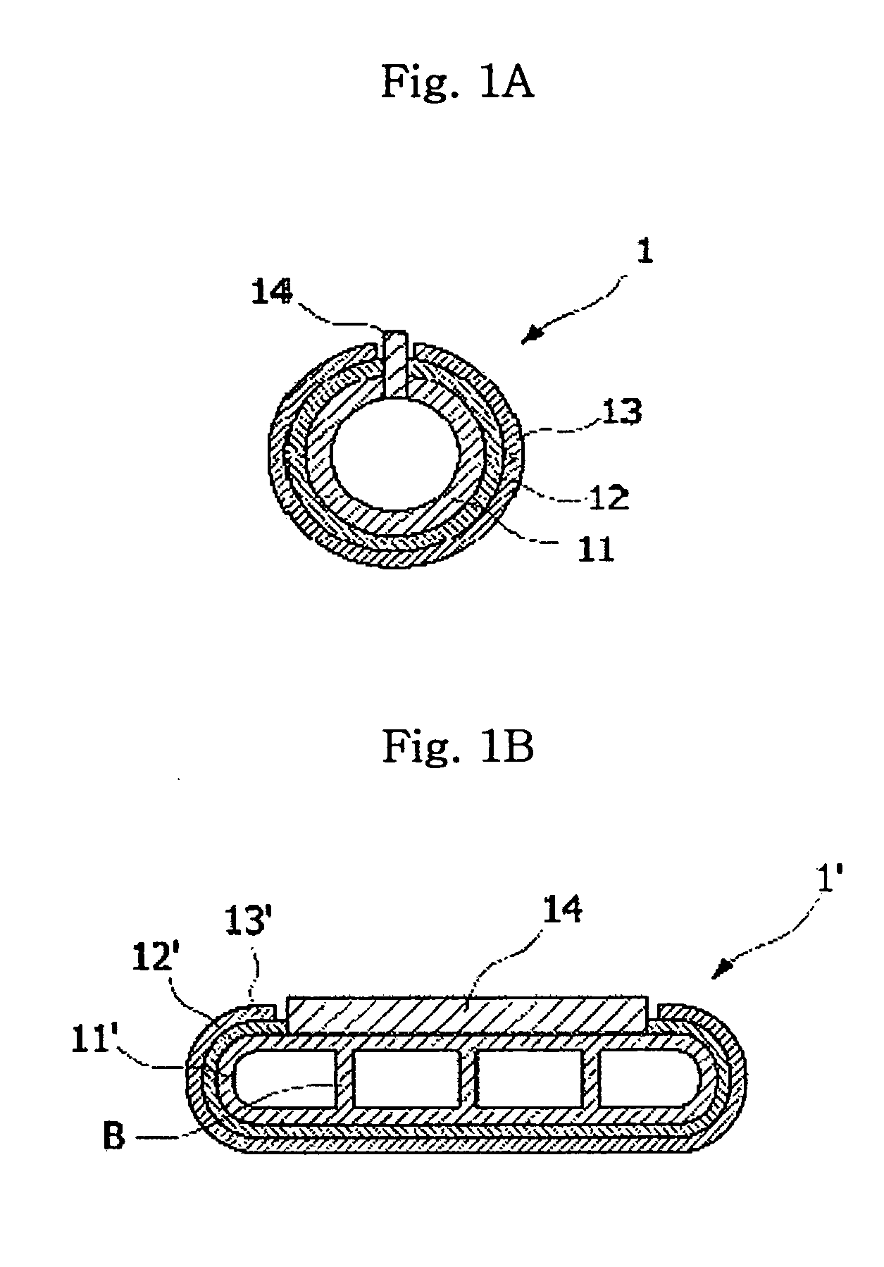
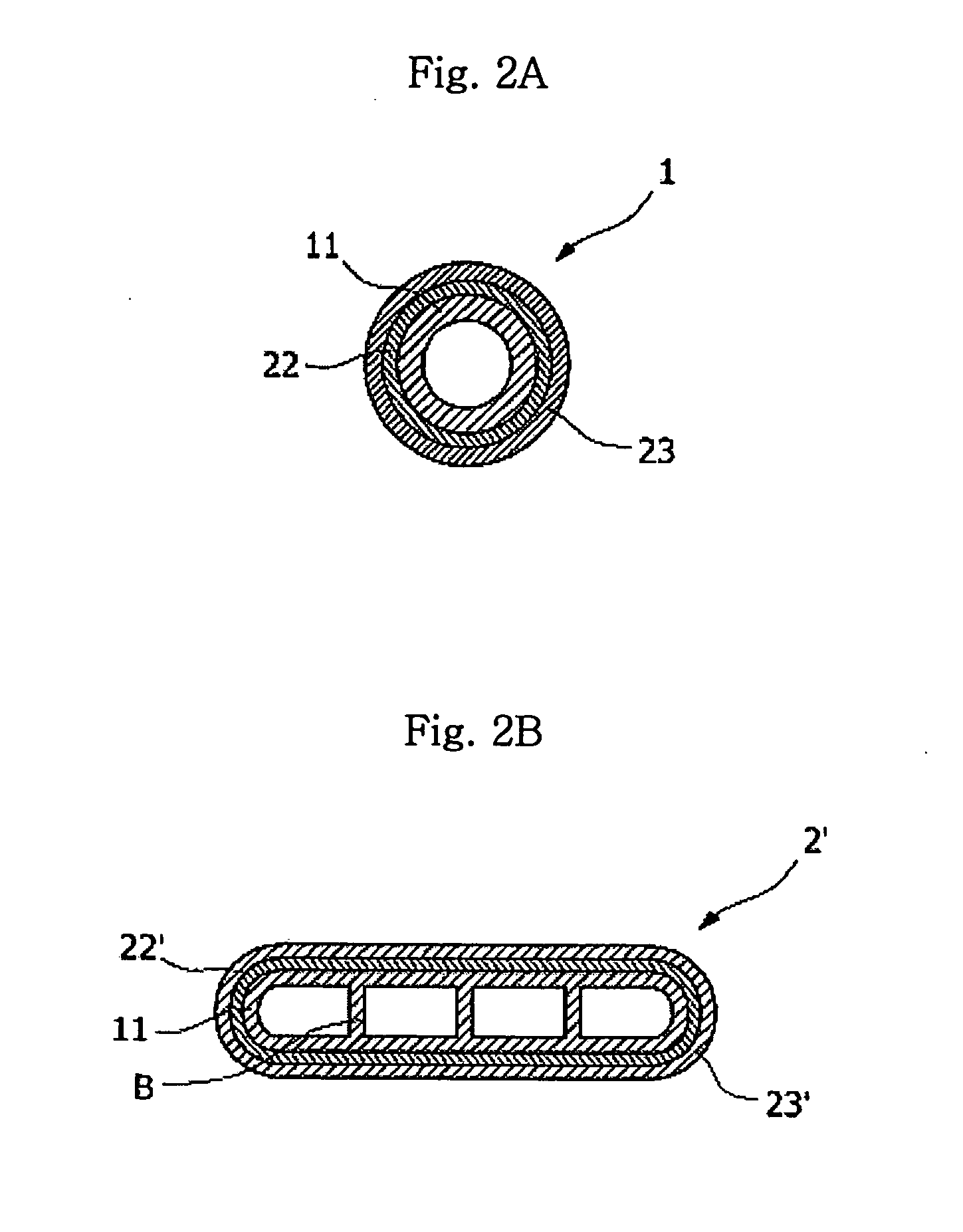
[0052]FIGS. 3A to 3C are perspective and sectional views illustrating an anode-supported cylindrical solid oxide fuel cell (SOFC), and FIGS. 4A to 4E are perspective and sectional views illustrating an anode-supported flat tubular SOFC.

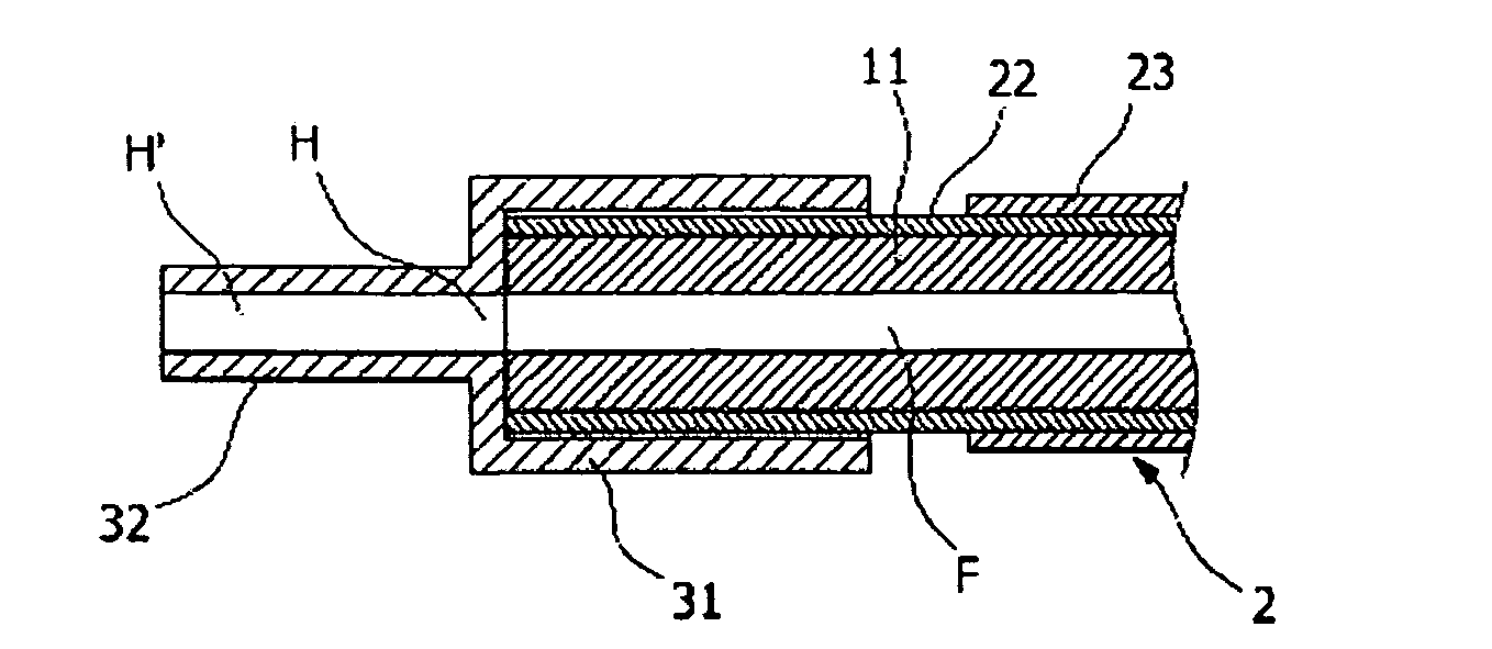
[0053]As shown in FIGS. 3A to 4E, the present invention provides two types of sealing elements according to the shape of the tubular fuel cell inserted into the sealing element. When the sealing element is incorporated with a cylindrical fuel cell 2, the sealing element has a metallic cap structure and is coupled to both ends of the fuel cell 2. In this case, the sealing element includes a coupling tube 31 having a ...


PUM


Abstract

Disclosed are a sealing element and a sealing method for sealing both ends of an anode-supported tubular solid oxide fuel cell. The sealing element includes a coupling tube having a first end portion opened to an exterior and a second end portion having a perforation hole, in which the coupling tube is formed with an internal cavity having a shape corresponding to an external appearance of an end portion of the fuel cell; and a flow tube extending outward from the center of the second end portion of the coupling tube and being formed with a hollow section, which axially extends while communicating with the perforation hole of the coupling tube. The sealing method includes the steps of cleaning the sealing element and the fuel cell; surrounding an outer peripheral surface of an electrolyte layer formed on both ends of the fuel cell with a metallic filler material such that the electrolyte layer does not make contact with a cathode, inserting the fuel cell into a connection tube of the sealing element, heating and melting the metallic filler material, and solidifying the melted metallic filler material. The sealing element improves the endurance and performance of the fuel cell. Since it is possible to use the sealing element as an anode collector, a fuel cell stack having a simple structure is realized.

Description

BACKGROUND OF THE INVENTION[0001]1. Field of the Invention[0002]The present invention relates to a cap type metallic sealing element, which is coupled to both ends of an anode-supported tubular solid oxide fuel cell having various sectional shapes, such as a cylindrical shape or a flat tubular shape, so as to easily and precisely seal the both ends of the anode-supported tubular solid oxide fuel cell such that the anode-supported tubular solid oxide fuel cell can efficiently collect electric charges, and a method for sealing both ends of an anode-supported tubular solid oxide fuel cell by coupling a cap type metallic sealing element to the both ends of the anode-supported tubular solid oxide fuel cell by means of brazing.[0003]2. Description of the Prior Art[0004]A fuel cell technology is a highly efficient clean power generation technology capable of directly converting hydrogen contained in hydrocarbon based materials, such as natural gas, coal gas or methanol, and oxygen containe...

Claims


Application Information

Patent Timeline
IPC IPC(8): H01M2/08H01M8/12B05D5/12
CPCH01M8/0276H01M8/0282Y02E60/525H01M8/1246Y02E60/521H01M8/0286Y02E60/50Y02P70/50H01M8/02H01M8/0258
Inventor SONG, RAK-HYUNSHIN, DONG-RYULLIM, TAK-HYUNGKIM, JONG-HEECHUNG, DONG-YOUSON, HUY-JEONG
Owner KOREA INST OF ENERGY RES
Why Eureka
Try Eureka