
Transmitter and power amplifying method

a technology of amplifier and amplifier, applied in the field of transmitter, can solve the problems of extremely significant out-of-band power, low power efficiency of amplifier of this type, peak regrowth, etc., and achieve the effects of improving amplifier power efficiency, reducing papr, and high papr

Inactive Publication Date: 2007-10-04
FUJITSU LTD
View PDF11 Cites 24 Cited by
  • Summary
  • Abstract
  • Description
  • Claims
  • Application Information

AI Technical Summary

Benefits of technology

[0016] The present invention has an object to provide a technique capable of reducing a PAPR in a communication system employing a modulation process exhibiting a high PAPR.
[0017] Further, the present invention has an object to provide a technique capable of improving a power efficiency of an amplifier in a communication system employing a modulation process exhibiting a high PAPR.
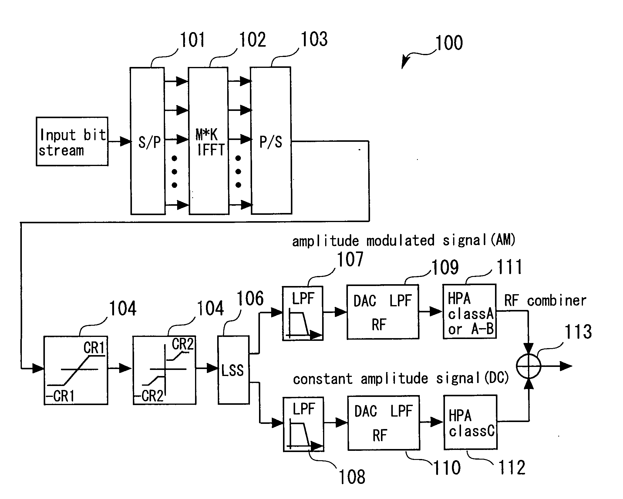
[0026] According to the present invention, in the first clipping and the second clipping, a high peak part and a low peak are cut out from the input signal to be subjected to power amplification. Accordingly, compared to the single clipping method, it is possible to reduce the PAPR, increase the signal power, and suppress occurrence of nonlinear distortion. Further, the present invention is configured such that the signal to be subjected to power amplification is separated into the amplitude modulated part (AM part) and the constant amplitude part (DC part) to be amplified separately, thereby allowing efficient amplification of a high PAPR signal.
[0029] Further, with the transmitter according to the present invention, it is preferable that the second amplifier have more satisfactory power efficiency than the first amplifier. Accordingly, it is possible to improve the power efficiency relating to amplification with respect to the entire signal to be subjected to the power amplification.
[0035] According to the present invention, it is possible to reduce a PAPR in a communication system (for example, an OFDM-based communication system) employing a modulation process exhibiting a high PAPR.
[0036] Further, according to the present invention, it is possible to improve a power efficiency of an amplifier in a communication system (for example, an OFDM-based communication system) employing a modulation process exhibiting a high PAPR.

Problems solved by technology

However, the amplifier of this type is low in power efficiency.
However, the signal must be interpolated before digital-to-analogue conversion, which may cause peak re-growth.
However, such the scheme causes extremely significant out-of-band power.

Method used


Image

  • Transmitter and power amplifying method
  • Transmitter and power amplifying method
  • Transmitter and power amplifying method

Examples


specific example

[0070] Next, description will be made of a specific example of an OFDM signal processing performed by the OFDM transmitter 100 having the configuration shown in FIG. 4. The M OFDM samples of every OFDM block are independent identically-distributed Gaussian random variables. Such statistical independence is responsible for high variability of the OFDM signal, making its PAPR extremely high.

[0071] As an example, the OFDM block signal (M=64, K=2, and M*K=128) amplitude A(n) at the IFFT processor 102 is indicated in FIG. 7 as a function derived from an OFDM sample number n.

[0072]FIG. 8 shows an amplitude of an OFDM signal identical to the OFDM signal shown in FIG. 7 within an output (CR=1.8 [dB]) from the first limiter 104, as a function derived from an OFDM sample number n. As shown in FIG. 8, in this embodiment, the first limiter 104 clips (cuts), from the OFDM signal, an amplitude part at an amplitude level higher than 0.10 as the amplitude part at the level higher than the clippin...


PUM


Abstract

A transmitter includes a first limiter for performing a first clipping in which an amplitude part at a level higher than an amplitude level based on a first clipping level is cut out from an input signal to be subjected to power amplification, a second limiter for performing a second clipping in which an amplitude part at a level lower than the amplitude level based on a second clipping level is cut out from a first signal that has undergone the first clipping, a separation section for separating a second signal that has undergone the second clipping into an amplitude modulated part and a constant amplitude part, a first amplifier for amplifying the amplitude modulated part, a second amplifier for amplifying the constant amplitude part, and a combiner for outputting a third signal obtained by combining the amplitude part amplified by the first amplifier and the constant amplitude part amplified by the second amplifier.

Description

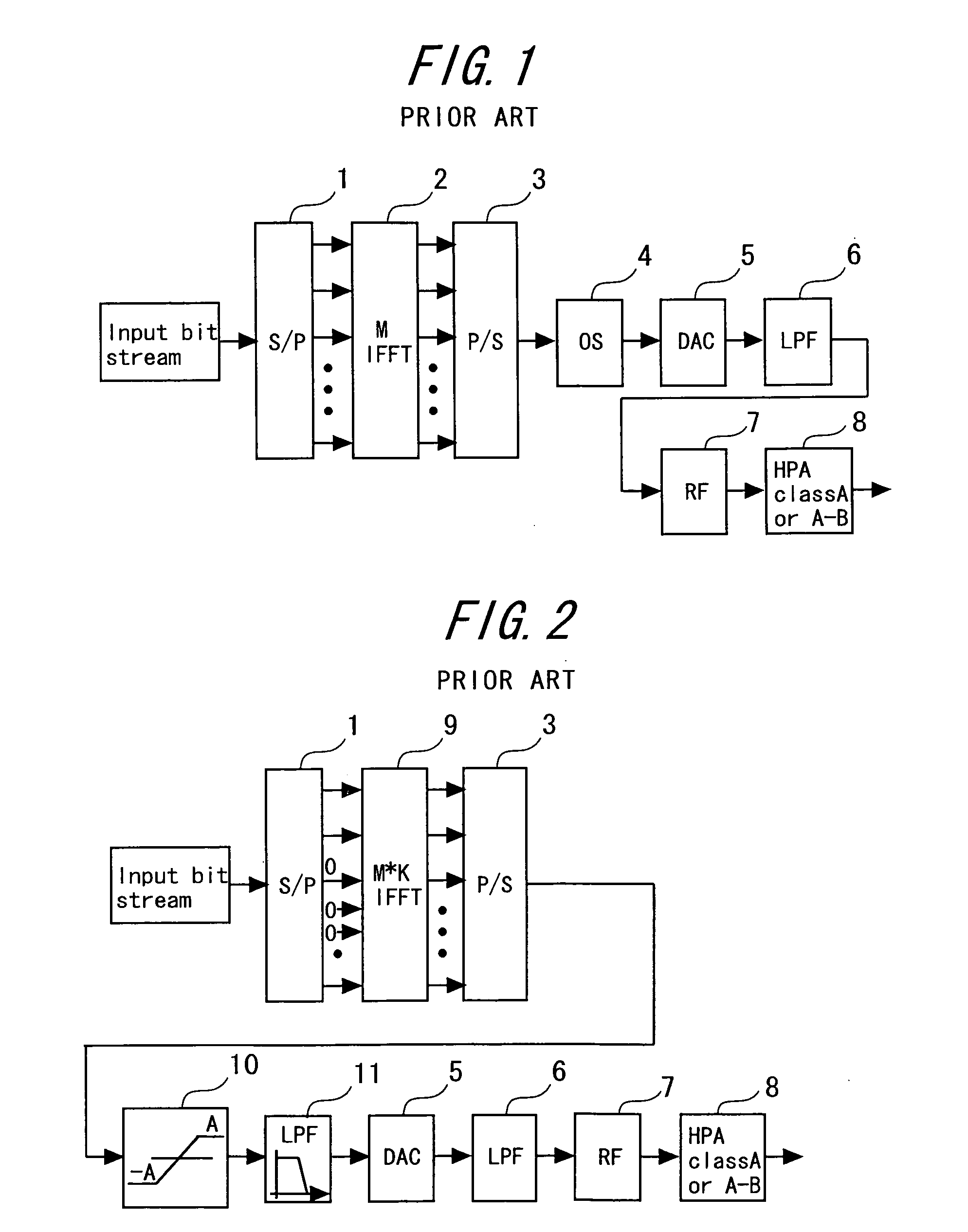
BACKGROUND OF THE INVENTION [0001] 1. Field of the Invention [0002] The present invention relates to a transmitter used for a communication system having a high peak-to-average power ratio (PAPR), and more particularly, to an amplifier and an amplifying method. Known examples of a system having a high PAPR include an OFDM (orthogonal frequency division multiplexing) communication system. [0003] 2. Description of the Related Art [0004]FIG. 1 shows a typical OFDM transmitter. As shown in FIG. 1, the OFDM transmitter includes: a serial-to-parallel converter (S / P) 1 for performing serial-to-parallel conversion on an input bit stream (source of data to be transmitted); an inverse fast Fourier processor (IFFT) 2 having a size of M; a parallel-to-serial converter (P / S) 3; an oversampling block (interpolator) (OS) 4; a digital-to-analog converter (DAC) 5; an output low-pass filter (LPF) 6; an RF up converter (RF) 7; and a high-power amplifier (HPA) 8 that operates in class A or class A-B. [...

Claims


Application Information

Patent Timeline
Patent Type & Authority Applications(United States)
IPC IPC(8): H04B1/02
CPCH03C5/00H04L27/2623H03F3/68H03F3/189
Inventor LOZHKIN, ALEXANDERTAKANO, TAKESHI
Owner FUJITSU LTD
Learn More