Method and Apparatus for Sampling and Analysis of Fluids

a fluid sampling and fluid technology, applied in the field of fluid sampling and analysis methods and apparatuses, can solve the problems of inability to reverse to eject, deposit or retake samples, and the device has disadvantages for blood glucose determination application to blood sampling

Active Publication Date: 2007-10-04
MICROSAMPLE
View PDF28 Cites 126 Cited by
  • Summary
  • Abstract
  • Description
  • Claims
  • Application Information

AI Technical Summary

Benefits of technology

[0029] In this way, the present invention allows the taking and / or transferring of blood, ISF or other samples that exist in a fluid or semi-fluid state (e.g. tissue samples such as biopsies) and / or depositing a fluid to the skin.
[0072] In preferred uses, the device can eliminate the need to use separate devices for piercing the skin, sampling and metering the blood or fluid. Preferred embodiments of the device allow transfer of the fluid sample to a sensor or analysis chamber. Further embodiments are capable of delivering a fluid to the skin before piercing. The device may be operated under automated control.

Problems solved by technology

Taking a blood sample by either of these methods can be painful for the patient / subject, and can cause distress, particularly in the case of diabetes sufferers who may have to take several blood samples a day.
The present inventors have realised that capillary-based sampling systems work well for many applications, but they do have the disadvantages that there is no control over the timing and rate of sampling once the capillary is presented to the sample; liquid generally will not flow from a narrow diameter capillary to a capillary or sensor chamber of larger diameter; they cannot deliver a fluid to the skin before lancing; most configurations have no provision for ejecting a sample; and they cannot be reversed to eject, deposit or re-take a sample.
The device has disadvantages for application to blood sampling for blood glucose determination and POC.
The lancet must be fully extended to attempt to eject all the contents, and thus presents a risk of injury.
The device of US2003 / 0088191 is also not suitable for the procedure of first lancing the subject's skin, allowing a droplet of blood to collect on the skin and then aspirating the droplet of blood.
The device is also not particularly suited to delivering a small sample of blood back out through the original sampling orifice.
The use of a diaphragm driven by air and the compressibility of the air headspace can make it very difficult to exert close control over the sampling and dispensing volumes.
The separation of the piston and sample has the disadvantage that it is difficult or impossible accurately to meter the volume of blood drawn into the device.
The inventor describes a disadvantage of U.S. Pat. No. 4,653,513, where the friction of the piston seal in the device is detrimental to the lancing action.
This should result in significant swelling at the puncture site.
Microneedles are generally more invasive than lancets because the needle has to be of sufficient diameter to be hollow.
These devices can aspirate and dispense fluids to high accuracy, but have no capability to pierce the skin or to affect an analysis.

Method used


Image

  • Method and Apparatus for Sampling and Analysis of Fluids
  • Method and Apparatus for Sampling and Analysis of Fluids
  • Method and Apparatus for Sampling and Analysis of Fluids

Examples


example 1

[0168] A device according to an embodiment of the present invention was fabricated by Cambridge Product Development Ltd (Huntingdon, Cambridge, England).

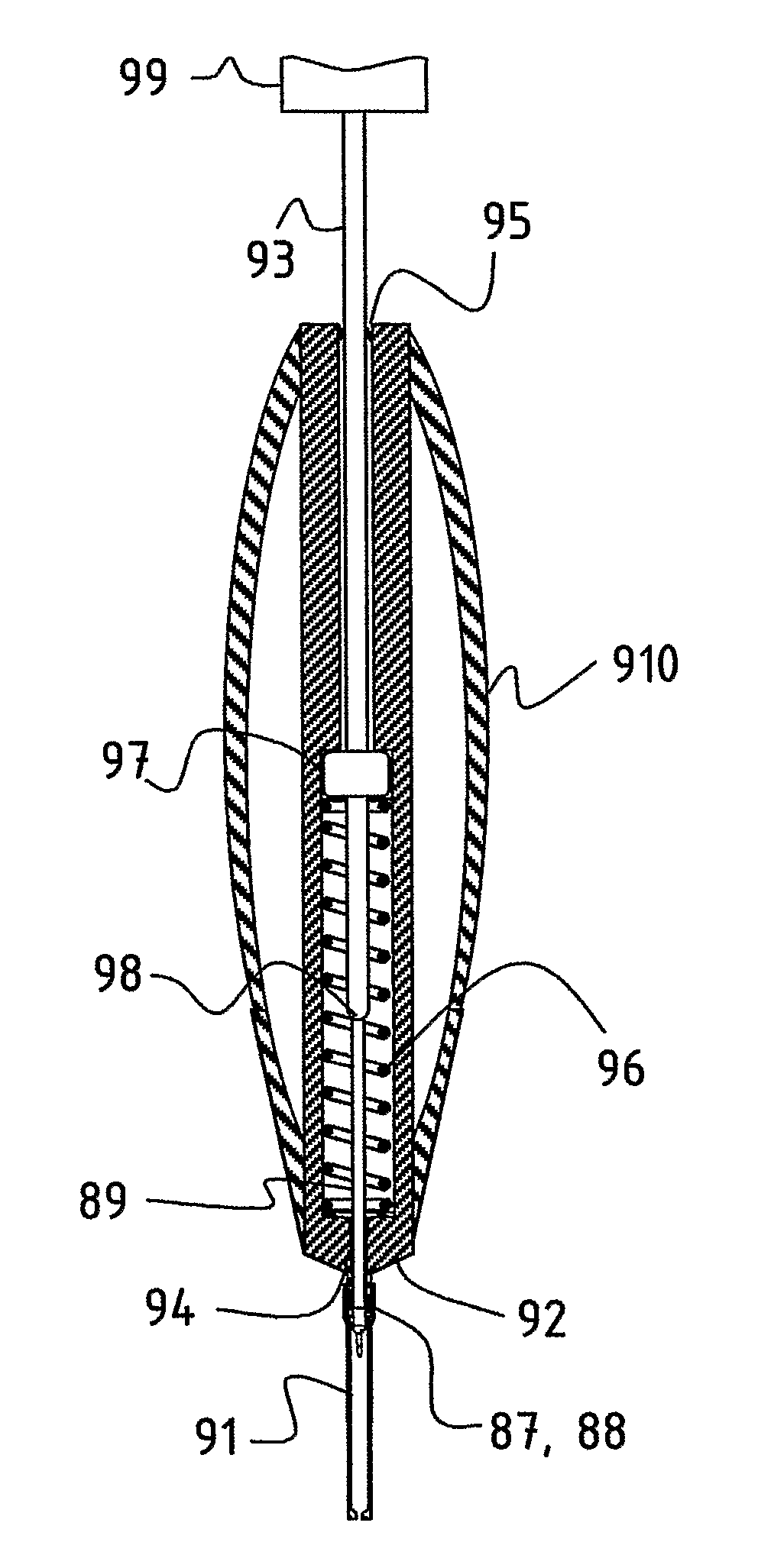
[0169] With reference to FIG. 18 (plan view), the device consists of a housing 182 of 2 cm length and 5 mm width incorporating a 0.67 mm diameter bore 183. A chamber 184 of 2 mm diameter×0.5 mm (approximately) high is connected to the bore. The position of this chamber is approximately 3 mm from the forward end of the bore. It can be appreciated that if this chamber were positioned at the forward end of the bore the fluid would be drawn directly into the chamber before any section of the bore. A lancet piston 181 of 0.67 mm OD and 32 mm length overall is inserted into this bore with the lancet point orientated towards the chamber end of the device. The lancet piston is provided with a feature 186 to enable the lancet piston to be gripped more easily. The volume of the bore is approximately 0.35 microliters per mm length and the vol...

example 2

[0182] A device according to an embodiment of the present invention may be fabricated by the following method.

[0183] A disposable syringe of 1 ml capacity (Becton Dickinson Plastipak) is adapted by first withdrawing the plunger rod completely and removing the rubber piston from the front end of the plunger rod. A counter bore of 1 mm diameter and 6 mm deep is drilled into the center of the front end of the plunger rod to accept a lancet tip.

[0184] A lancet tip is provided by cutting the plastic off a disposable “Softclix” lancet (Boehringer Mannheim) to recover a lancet of 0.75 mm diameter and 25 mm long with a ground lancet tip. The lancet is glued into the hole prepared in the front end of the plunger rod. The rubber piston is pierced through the center by the lancet, and is threaded along the lancet before being seated onto the end of the plunger rod. This results in the construction of a composite lancet piston with a piston seal. This assembly is inserted into the bore of the...


PUM


Abstract

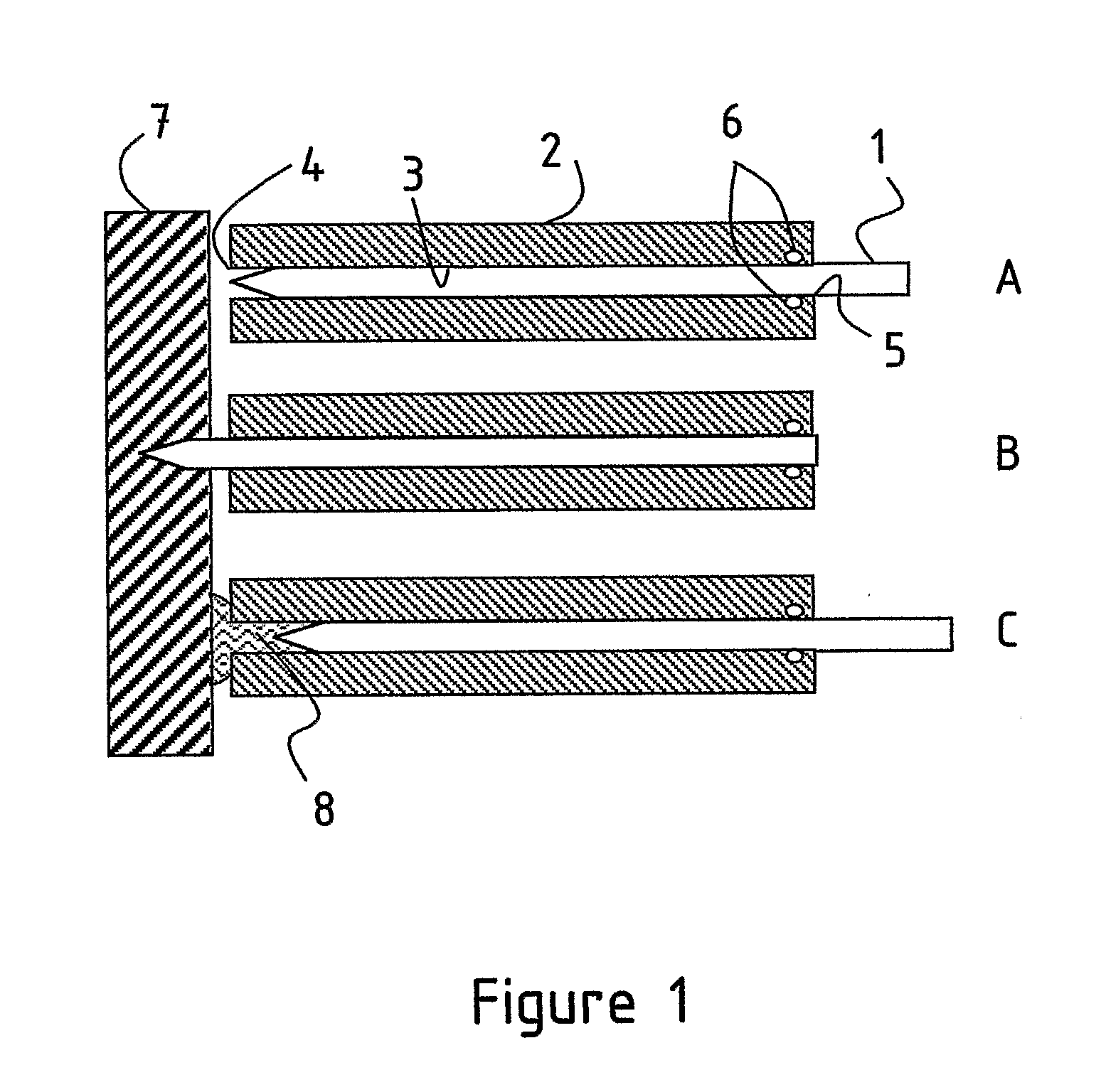
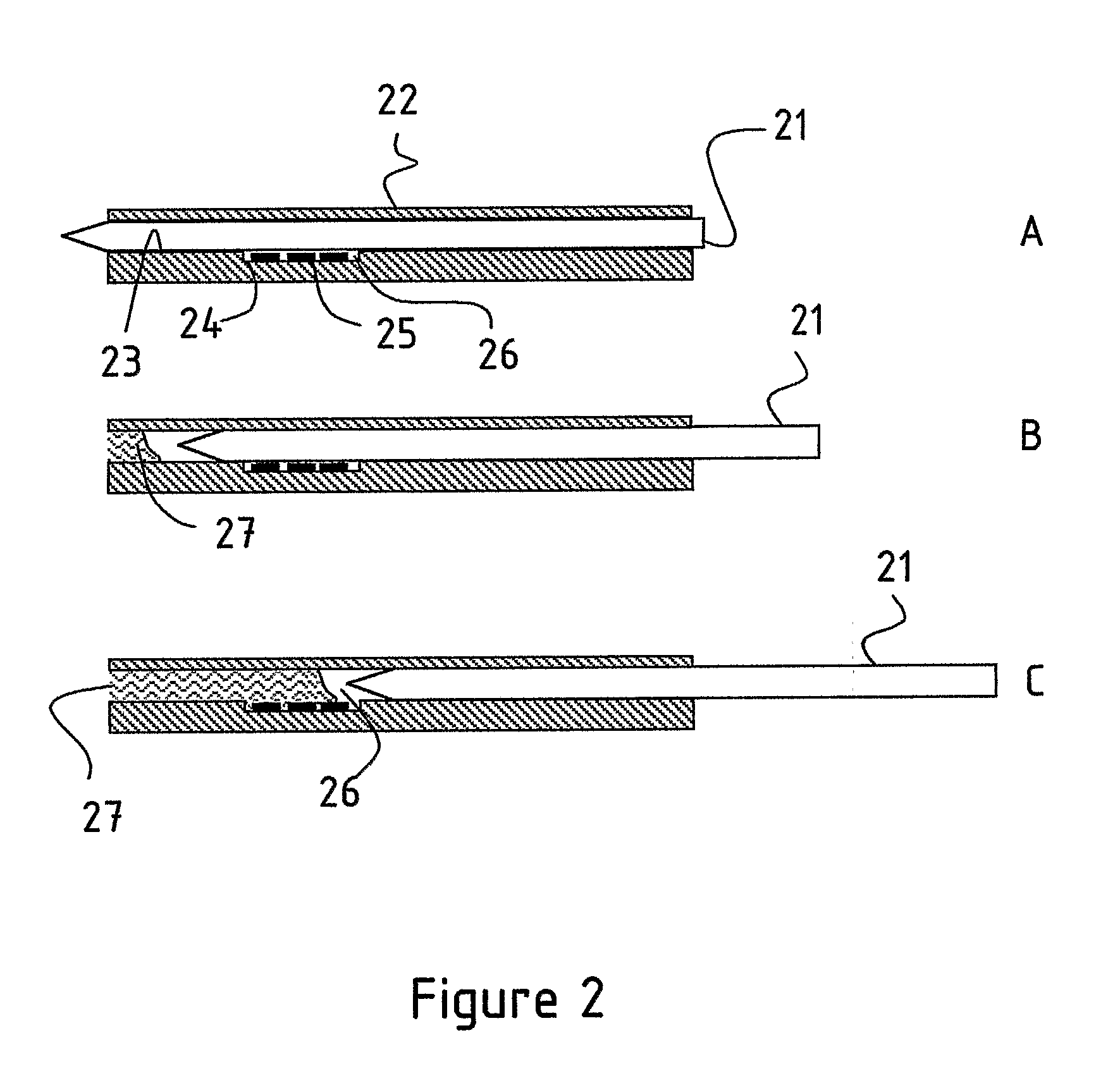
A medical device having a housing (2) with a bore (3) and a lancet (1) slidably fitting in the bore. The lancet operates as a positive displacement piston. In a retracted position, in which the lancet is rearwardly displaced along the bore to define a fluid-containing space in the bore forwardly on the lancet tip, the fluid-containing space has a cross-section dimension to allow fluid to be retained therein by surface tension. The device has a seal (6) operable substantially to prevent flow of fluid from the fluid-containing space past the seal means on movement of the lancet. Displacement of the lancet between the puncture and retracted positions provides suction for drawing fluid into and along the fluid-containing space from the forward end of the bore, and / or pressure for expelling fluid from the fluid-containing space via the forward end of the bore. Also disclosed are methods for operating the device.

Description

BACKGROUND TO THE INVENTION [0001] 1. Field of the Invention [0002] This invention relates to a sampling and / or dispensing method and apparatus for performing the same. There are many occasions where body fluid samples have to be collected by first piercing the skin and then sampling a fluid, such as blood or interstitial fluid (ISF), or cells contained within. A very important application is the sampling of blood or ISF for various analyses, for example blood glucose, electrolytes or cholesterol. In some applications, for example in the use of Point of Care (POC) instruments, it is important to provide an accurately metered sample of fluid to the instrument. There are also advantages to being able to deposit a fluid (for example antiseptic) on the skin before making an incision. [0003] 2. Related art [0004] The most commonly used blood sampling devices are the hypodermic syringe and lancet. Taking a blood sample by either of these methods can be painful for the patient / subject, and...

Claims


Application Information

Patent Timeline
Patent Type & Authority Applications(United States)
IPC IPC(8): A61B5/15A61B5/00
CPCA61B5/1411A61B5/14532A61B17/205A61B5/441A61B5/411A61B5/150022A61B5/150167A61B5/150183A61B5/15019A61B5/150213A61B5/150236A61B5/150244A61B5/150358A61B5/150435A61B5/150503A61B5/150587A61B5/150717A61B5/150755A61B5/150946A61B5/15105A61B5/15113A61B5/1519A61B5/15194
Inventor HARMAN, ANTHONY DAVIDCASSELLS, JOHN MACLAREN
Owner MICROSAMPLE
Why Eureka
Try Eureka