Mass flow rate control apparatus, its calibration method and semiconductor-producing apparatus

a flow rate control and flow rate technology, applied in the direction of fluid pressure measurement by mechanical elements, testing/calibration of speed/acceleration/shock measurement devices, volume flow measurement devices, etc., can solve the problems of insufficient accuracy of mass flow rate control calibration, easy calibration errors, and complicated apparatus structur

Active Publication Date: 2007-10-04
HITACHI METALS LTD
View PDF11 Cites 78 Cited by
  • Summary
  • Abstract
  • Description
  • Claims
  • Application Information

AI Technical Summary

Benefits of technology

[0034]The method of the present invention for calibrating a mass flow controller comprising a calibrating valve disposed on the most upstream side of the path, a mass flow rate control valve mechanism, a tank provided at the path upstream of the mass flow rate control valve mechanism, a mass-flow-rate-sensing means, a pressure-sensing means, a means for controlling the mass flow rate control valve mechanism, and a mass flow rate calibration control means, the method comprising the steps of (1) permitting a fluid at a set mass flow rate to flow through the path, (2) setting the mass flow rate control valve mechanism at a degree of opening that the mass flow rate of the fluid is equal to the set mass flow rate, (3) closing the calibrating valve, (4) measuring the pressure Pf and mass flow rate Rf of the fluid after a fluid flow from the tank is stabilized, (5) determining a calibrating comparator Af represented by a ratio of the product ΔPf×V

Problems solved by technology

However, because this method uses the reservoir outlet isolation valve between the reservoir and the mass flow rate control valve, and a pressure-sensing means and an orifice between the mass flow rate control valve and the isolation valve, the overall structure of the apparatus is complicated, and the reservoir should have a large volume.
Further, because the first and second signals each indicating a mass determined from the sensed pressure are compared, the mass signal is subjected to the same de

Method used


Image

  • Mass flow rate control apparatus, its calibration method and semiconductor-producing apparatus
  • Mass flow rate control apparatus, its calibration method and semiconductor-producing apparatus
  • Mass flow rate control apparatus, its calibration method and semiconductor-producing apparatus

Examples


Embodiment Construction

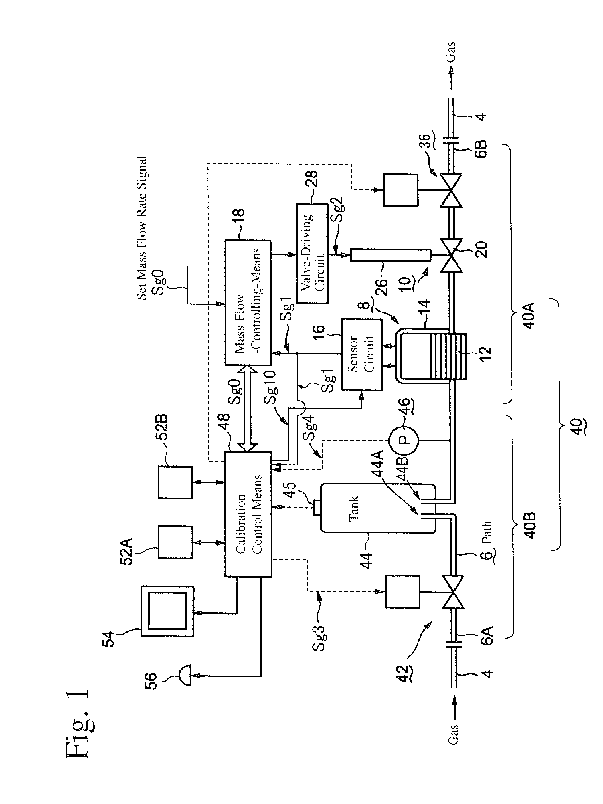
[0036]FIG. 1 is a block diagram showing one example of the mass flow controller of the present invention.

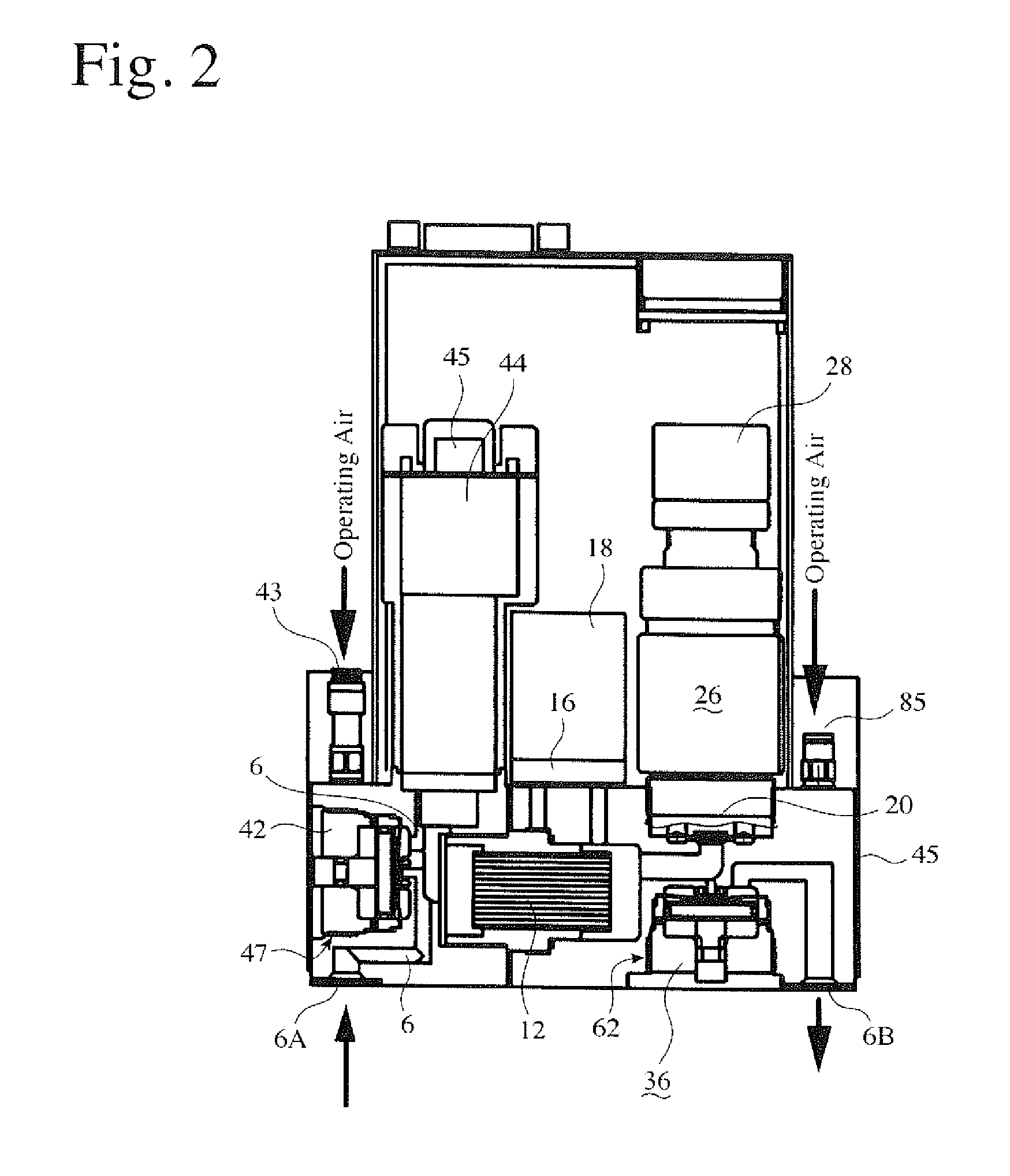
[0037]FIG. 2 is a schematic cross-sectional view showing the internal structure of the mass flow controller of the present invention.

[0038]FIG. 3(a) is a graph showing the variation of mass flow rate and pressure with time.

[0039]FIG. 3(b) is a graph showing the relation between the product of pressure drop and a tank volume and an integral value of the mass flow rate.

[0040]FIG. 4 is a chart showing the timing of each signal in the mass flow controller in a calibration mode.

[0041]FIG. 5 is a flow chart showing the steps of the reference-data-obtaining routine.

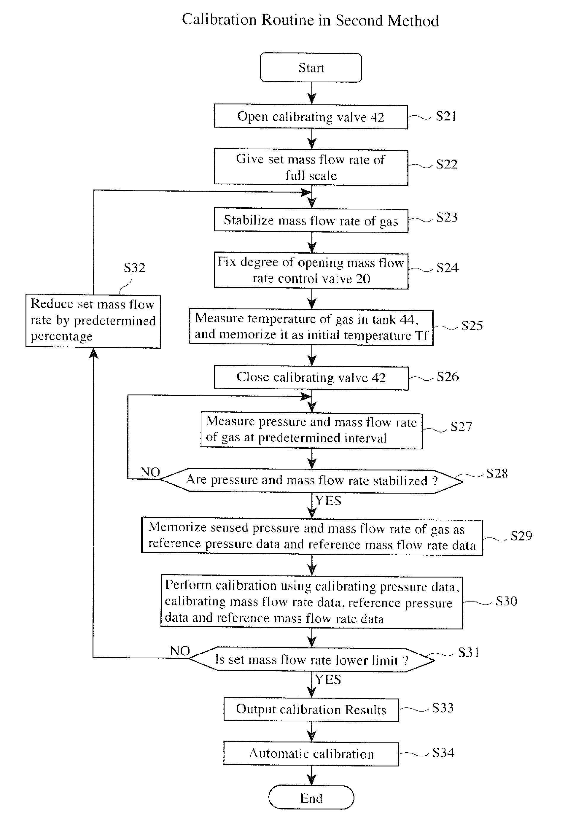
[0042]FIG. 6 is a flow chart showing the steps of the calibration routine in the first calibration method.

[0043]FIG. 7 is a flow chart showing the calibration steps in the calibration routine.

[0044]FIG. 8 is a graph showing the variation with time of a comparator A, a ratio ΔP×V / ΣR, wherein ΔP×V is the product of pressure dec...


PUM


Abstract

A method for calibrating a mass flow controller comprising a calibrating valve disposed on the most upstream side of a path, a mass flow rate control valve mechanism, a tank provided at the path on the upstream side of the mass flow rate control valve mechanism, a mass-flow-rate-sensing means, a pressure-sensing means, a means for controlling the mass flow rate control valve mechanism, and a mass flow rate calibration control means, the method comprising the steps of (1) permitting a fluid at a set mass flow rate to flow through the path, (2) setting the mass flow rate control valve mechanism at a degree of opening that the mass flow rate of the fluid is equal to the set mass flow rate, (3) closing the calibrating valve, (4) measuring the pressure and mass flow rate of the fluid after a fluid flow from the tank is stabilized, (5) determining a variation ratio of the pressure and mass flow rate to reference pressure and mass flow rate measured by the same procedures in an initial state, is and (6) performing calibration depending on the variation ratio.

Description

FIELD OF THE INVENTION[0001]The present invention relates to a mass flow controller capable of calibrating the accuracy of the mass flow rate control of a fluid at a relatively small flow rate, a method for calibrating such a mass flow controller, and a semiconductor-producing apparatus comprising such a mass flow controller.BACKGROUND OF THE INVENTION[0002]In general, when CVD, etching, etc. are conducted on semiconductor wafers in the production of semiconductors such as semiconductor integrated circuits, etc., mass flow controllers are used to control the amount of a treating gas supplied at high accuracy.[0003]FIG. 13 shows a conventional mass flow controller 2 disposed in the course of a path (for instance, gas pipe) 4 for flowing a fluid such as liquid, gas, etc. The mass flow controller 2 comprises a path 6 made of stainless steel, etc. with both ends connected to a gas pipe 4, a mass-flow-rate-sensing means 8 positioned on the upstream side of the path 6, a mass flow rate co...

Claims


Application Information

Patent Timeline
IPC IPC(8): G06F19/00G01F25/00G01F1/12G05D7/06
CPCG01F1/6847G01F25/0007G01F15/043G01F5/00G05D7/0635Y10T137/0324Y10T137/7759G01F25/10G05D7/06
Inventor GOTOH, TAKAOHAYASHI, AKIFUMIMATSUOKA, TOHRUSUZUKI, SHIGEHIROFURUKAWA, YOSHIYUKITANAKA, MAKOTO
Owner HITACHI METALS LTD
Why Eureka
Try Eureka