Communication apparatus
- Summary
- Abstract
- Description
- Claims
- Application Information
AI Technical Summary
Benefits of technology
Problems solved by technology
Method used
Image

Examples
first embodiment
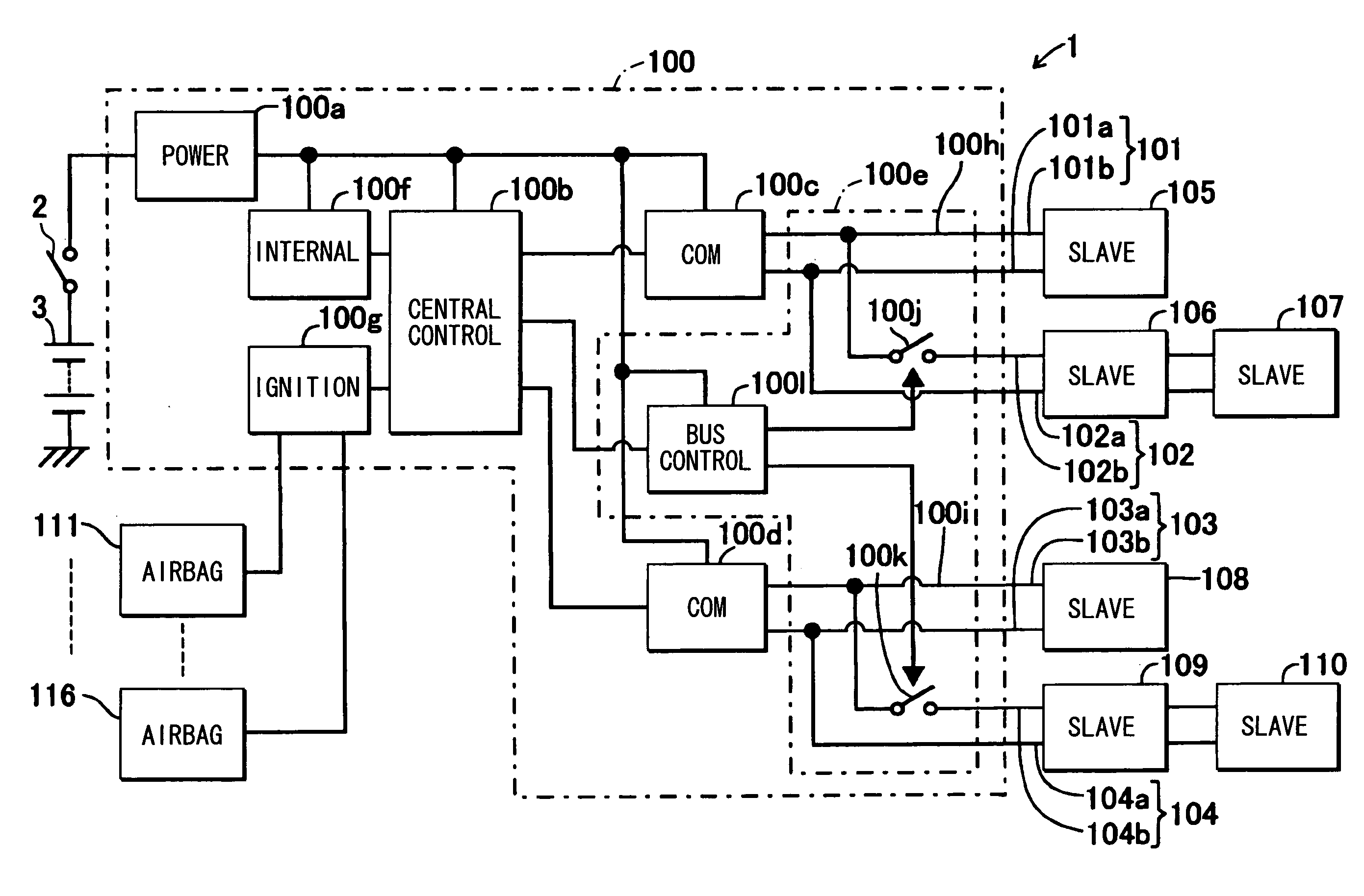
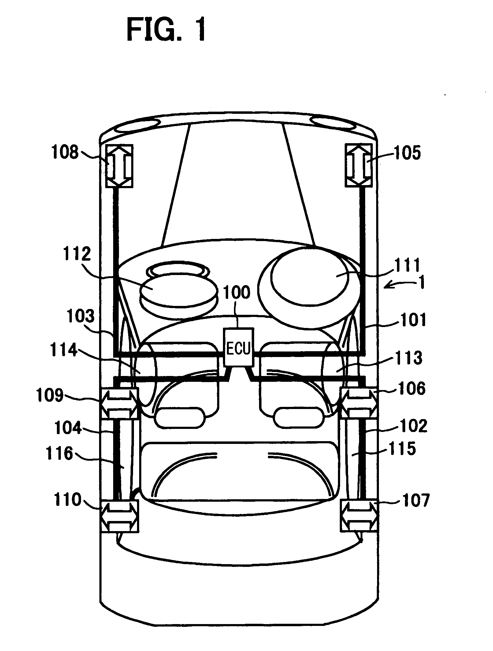
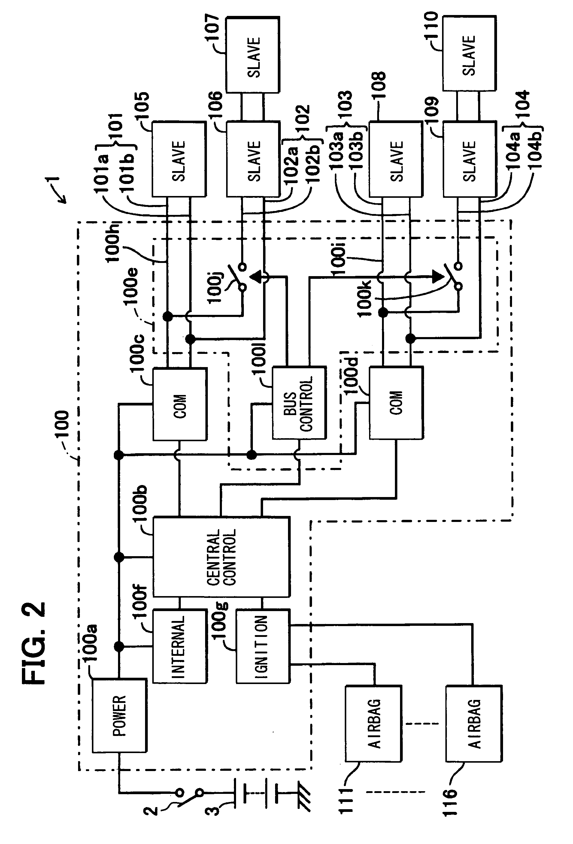
[0016]Referring first to FIG. 1, an airbag apparatus 1 (communication apparatus) includes an airbag ECU 100 (master device or electronic controller), communication buses 101 to 104, slave sensor devices 105 through 110 (slave devices or sensors), a front airbag 111 for a driver's seat, a front airbag 112 for a passenger seat, side airbags 113 and 114, and curtain airbags 115 and 116.
[0017]The airbag ECU 100 is for inflating the driver's seat airbag 111, the passenger seat airbag 112, the side airbags 113 and 114, and the curtain airbags 115 and 116 based on acceleration detected by the slave sensor devices 105 through 110a and an internal sensor device 100f (FIG. 2) provided inside the ECU 100. The airbag ECU 100 is located substantially in the middle of the vehicle.
[0018]The communication buses 101 to 104 are signal lines for supplying voltages from the airbag ECU 100 to the slave sensor devices 105 through 110 and for allowing commands and data to be transmitted and received betwe...
second embodiment
[0044]In an airbag apparatus of the second embodiment, a communication bus connection circuit is different from the airbag apparatus 1 of the first embodiment.
[0045]As shown in FIG. 4, the communication bus connection circuit 100e of the airbag ECU 100 includes additionally bus switches 100n and 100o. The bus switches 100n and 100o are for connecting the communication buses 101 and 103 to the communication circuits 100c and 100d, respectively. The bus switches 100n and 100o are connected to the input / output ports of the communication circuits 100c and 100d, respectively, at one ends thereof and connected to transmission lines 101b and 103b of the communication buses 101 and 103, respectively, at the other ends thereof. The bus switch control circuit 100l controls the switching of the bus switches 100j, 100k, 100n and 100o based on control commands output from the central control circuit 100b. An input terminal of the bus switch control circuit 100l is connected to the central contro...
third and fourth embodiments
[0052]The first and second embodiments have addressed examples in which the slave sensor devices 105 through 107 for detecting acceleration at parts of a vehicle on the left side thereof are connected to the communication circuit 100c and in which the slave sensor device 108 to 110 for detecting acceleration at parts of the vehicle on the right side thereof are connected to the communication circuit 100d. However, the first and second embodiments may be modified as shown in FIGS. 5 (third embodiment) and 6 (fourth embodiment), respectively. In these embodiments, the slave sensor devices 105 and 108 for detecting acceleration at front parts of a vehicle may be connected to the communication circuit 100c, and the slave sensor device 106, 107, 109 and 110 for detecting acceleration at side parts of the vehicle may be connected to the communication circuit 100d.
PUM
 Abstract
Description
Claims
Application Information
 - Generate Ideas
- Intellectual Property
- Life Sciences
- Materials
- Tech Scout
- Unparalleled Data Quality
- Higher Quality Content
- 60% Fewer Hallucinations
Browse by: Latest US Patents, China's latest patents, Technical Efficacy Thesaurus, Application Domain, Technology Topic, Popular Technical Reports.
© 2025 PatSnap. All rights reserved.Legal|Privacy policy|Modern Slavery Act Transparency Statement|Sitemap|About US| Contact US: help@patsnap.com