Sighting device for a firearm and firearm with an installation possibility for a sighting device

a sighting device and firearm technology, applied in the direction of sighting devices, weapon components, weapons, etc., can solve the problems of inability to accurately identify the impact point, inevitably exhibit larger dimensions and weight, and avoid unnecessary exhaustion of the source of energy, and direct optical crosstalk from the sender

Inactive Publication Date: 2007-10-11
BLASER FINANZHLDG
View PDF4 Cites 3 Cited by
  • Summary
  • Abstract
  • Description
  • Claims
  • Application Information

AI Technical Summary

Benefits of technology

[0005] In view of this prior art, the task of the invention is to create a solution for measuring the distance while shooting, which facilitates the most compact and lightest construction of the sighting device possible and is distinguished by safe and comfortable operation.
[0009] In this case, the sighting device may also be assigned signal processing electronics to evaluate the signal received and to relay to the signal processing electronics via the interface the information still needed to determine the target distance, if necessary. In this case, the sender as well as the control electronics that generates the sending signal may be arranged on the firearm. The advantage in doing this is that, firstly, a direct optical crosstalk from the sender to the receiver is avoided without great expense. Second, the power consumption of the sender, which is generally higher in comparison to that of the receiver, may be covered by its own source of energy in the firearm, in which accommodating batteries in the shaft of a gun is much less problematic than in the housing of a sighting telescope.
[0010] A wireless, and in particular an optical implementation appears very expedient for the interface, in which matching the orientation of the two sides to one another is easily attainable due to the accurate, predetermined position of a correctly mounted sighting device on the barrel of a firearm.
[0011] A further advantage of the concept according to the invention exists in the possibility of placing a switch for manual on and / or off switching of the measuring device in an ergonomically convenient position, i.e., in particular in the case of a shoulder arm on the stock, where a shoulder arm is normally held with the other hand when firing. In this case, the marksman need not give up the normal firing stance in order to switch the measuring device on or off. Aside from the on / off switch, a manual brightness control for the display device may be provided or combined with the on / off switch.
[0012] Furthermore, it is also possible to couple operational organs of the firearm with one or several switches in the service circuit of the measuring device such that the latter is always switched on when the weapon is in firing position, and is then always switched off when the readiness for firing is cancelled. As a result thereof, prompt switching on of the measuring device cannot be forgotten on the one hand, and on the other hand, unnecessary exhaustion of the source of energy is avoided. This override may also be combined with a manual switch, which takes precedence over the override.

Problems solved by technology

When shooting in the course of hunting, the distance to the target may often be estimated relatively inaccurately by the marksman due to unfavorable lighting conditions or broken terrain, which results in a correspondingly inaccurate impact point.
Since fiddling around with a separate distance meter while hunting is undesirable for obvious reasons, sighting devices with an integrated distance meter were developed.
The disadvantage in such sighting telescopes with an integrated distance meter is that, in comparison to conventional sighting telescopes, they inevitably exhibit larger dimensions and greater weight.
If the marksman goes into firing position and readies the weapon to fire, without first switching on the distance meter, he must hold the ready-to-fire weapon with one hand in order to switch it on subsequently, which is undesirable from a safety standpoint.

Method used


Image

  • Sighting device for a firearm and firearm with an installation possibility for a sighting device
  • Sighting device for a firearm and firearm with an installation possibility for a sighting device

Examples


Embodiment Construction

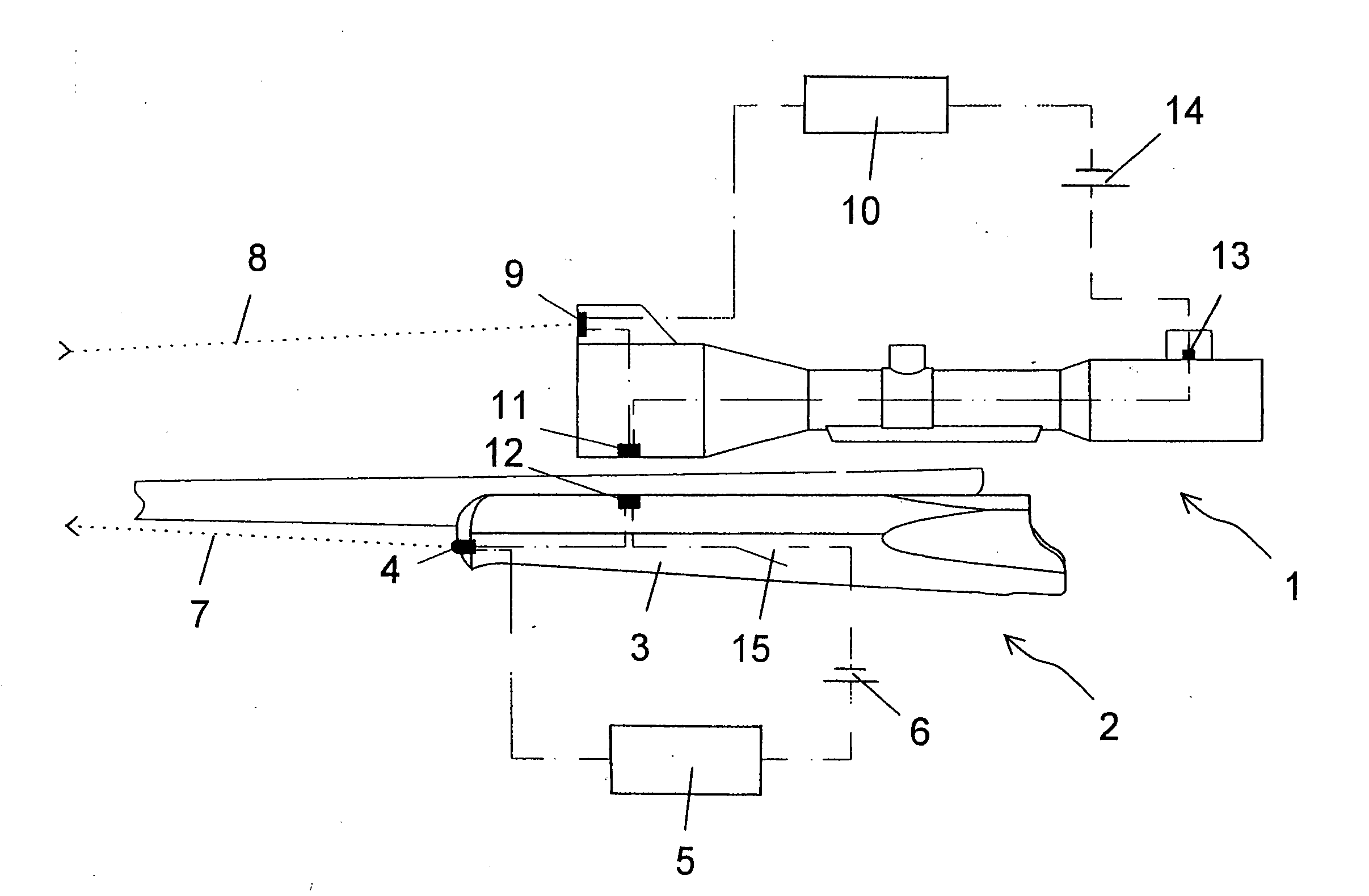
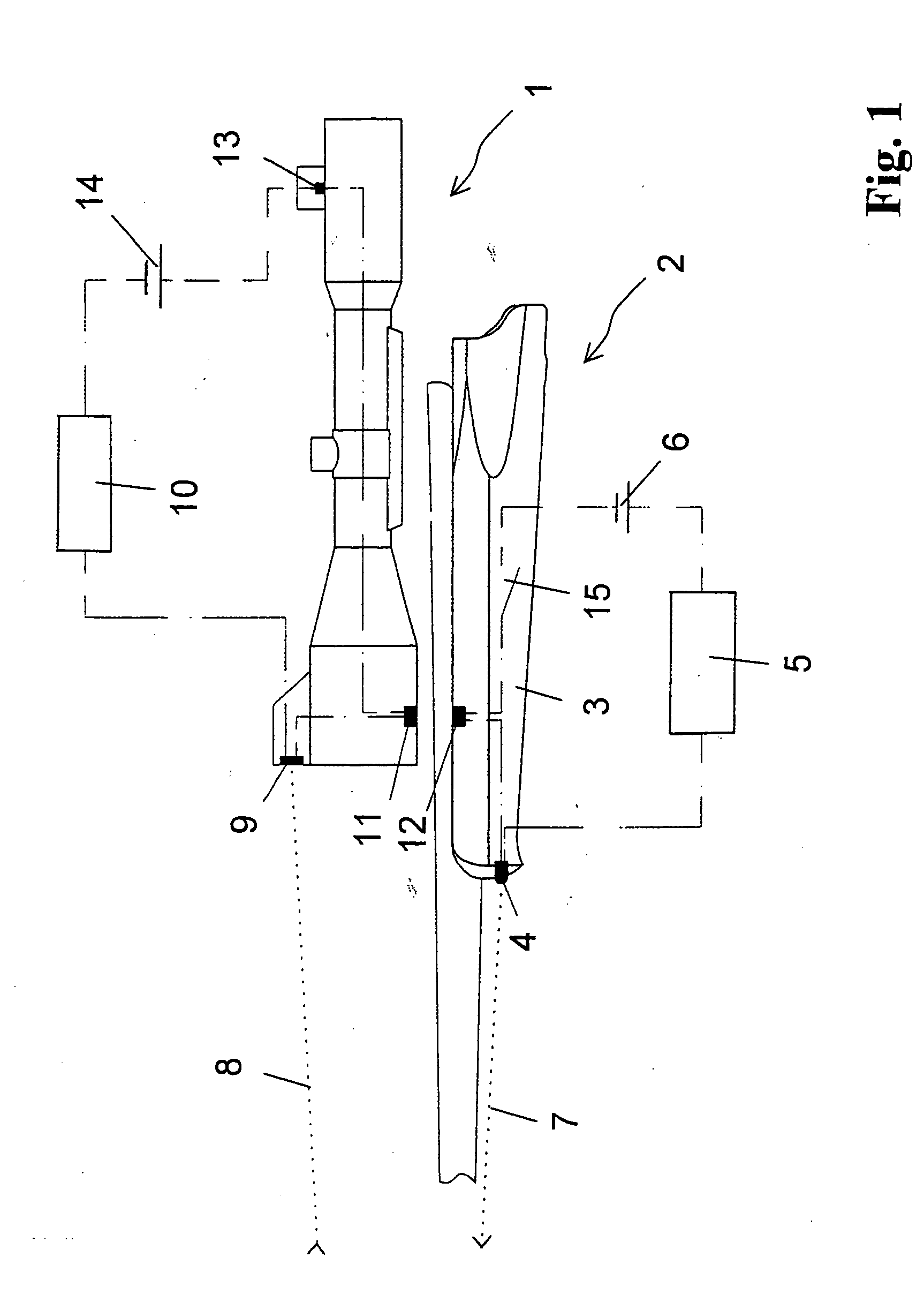
[0014]FIG. 1 shows a sighting device 1 in the form of a sighting telescope, which is fastened onto a firearm 2 in the form of a hunting rifle by means of an unillustrated assembly of a known type. The sighting device 1 contains a lens system and a graticule, for example in the form of cross hairs, which are likewise not shown.

[0015] Arranged in the stock 3 of the firearm 2 are an optical sender 4 in the form of a laser diode, control electronics 5, which contains a signal generator for generating the signal to be emitted by the sender 4, as well as a source of energy 6 in the form of a battery to supply the sender 4 and the control electronics 5. The signal generator of the control electronics 5 generates a characteristic signal, which is emitted by the sender 4 toward the target by the marksman. For bundling the laser beam 7, a miniature lens system, not illustrated in the figure, may also be provided. The laser beam 8 reflected by the target falls on a receiver 9 arranged in the ...


PUM


Abstract

A sighting device for a firearm exhibits a display device, which is a component of a measuring device for the distance to the target and which displays this target in the field of vision of the marksman. Of the other components of the measuring device, at least one part is not arranged in or on the sighting device. The sighting device exhibits an interface, through which the components of the measuring device arranged in or on the sighting device may be connected to components of the measuring device arranged in or on the firearm in an assembly in accordance with the intended use of the sighting device on the firearm, in such a way that, as a result, collectively a measuring device in working order arises. To this end, the firearm also exhibits a corresponding interface as well, as one of the components of the measuring device.

Description

FIELD OF THE INVENTION [0001] The invention relates to a sighting device for a firearm, as well as, a firearm with an installation possibility for a sighting device. BACKGROUND OF THE INVENTION [0002] The correspondence of the point of impact of a firearm with the bull's eye, which the marksman is taking aim at using a sighting device fastened on the firearm, is generally given only for a single distance to the target from the weapon. In general, a firearm is therefore shot at a preferred target distance, i.e., the sighting device, while firing several shots at a target at this distance, is adjusted until said correspondence is achieved. For another target distance, a target different from the intended point of impact must be consciously aimed at by the marksman, or the sighting device must be adjusted in a suitable manner, for which knowledge of the actual target distance is necessary in each case. SUMMARY OF THE INVENTION [0003] When shooting in the course of hunting, the distance...

Claims


Application Information

Patent Timeline
Patent Type & Authority Applications(United States)
IPC IPC(8): F41G1/00F41GF41G1/387F41G1/473F41G11/00
CPCF41G1/387F41G11/001F41G1/473
Inventor SCHERPF, CHRISTIAN
Owner BLASER FINANZHLDG
Why Eureka
Try Eureka