Adaptive pattern correction for laser scanners

a laser scanner and pattern correction technology, applied in the field of laser scanners, can solve problems such as distortion of actual scan pattern, and achieve the effect of increasing scan rate and preserving scan pattern fidelity

Active Publication Date: 2007-10-11
AMO DEVMENT
View PDF21 Cites 77 Cited by
  • Summary
  • Abstract
  • Description
  • Claims
  • Application Information

AI Technical Summary

Benefits of technology

[0008] The present invention provides a method and apparatus for preserving scan pattern fidelity with increasing scan rate. The invention may be applied to adaptively cor

Problems solved by technology

Characteristically, the laser scanner introduces focal point positioning errors in response to scanning movement control signals that result in a distortion of the actual scan pattern.
Control signals developed t

Method used


Image

  • Adaptive pattern correction for laser scanners
  • Adaptive pattern correction for laser scanners
  • Adaptive pattern correction for laser scanners

Examples


example

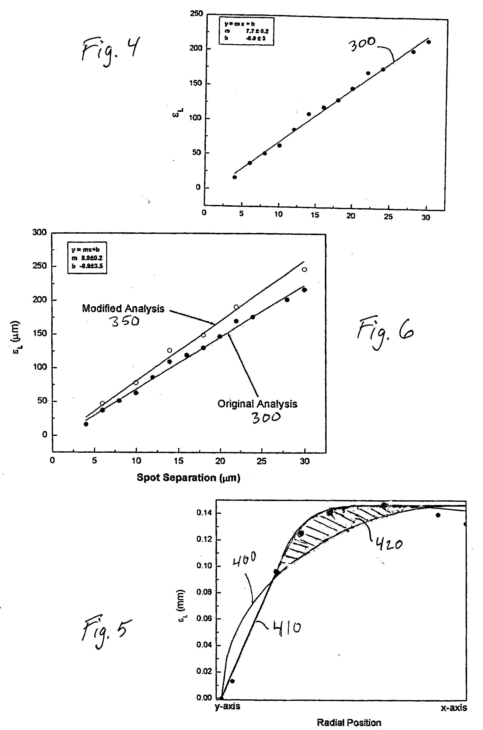
[0032] An FS2 30 kHz laser was programmed with different radial offset factors for spot separations of 4, 10, 16, 22 and 30 μm, using its factory settings. The laser was configured such that a radial offset of zero generated a theoretically (i.e., ignoring galvanometer lag) circular scan pattern. Entry of a positive radial offset would produce a theoretical elliptical output according to Eq. 1 above. The FS2 laser could also be programmed with an amount of horizontal offset, regardless of spot separation. Factory settings for the FS2 laser were determined and set using the following methodology: [0033] 1. Set the horizontal offset to 100 μm. [0034] 2. Set the radial offset to zero for all spot separations. [0035] 3. Cut 9 mm patterns in glass slides at three spot separations, e.g., 6, 12 and 18 μm. [0036] 4. Measure the amount of raster-side (x-axis) overlap at the 0° and 180° positions. [0037] 5. Select the set of values for the position (i.e., 0° and 180°) exhibiting the most unde...


PUM


Abstract

A system for adaptive laser scanning correction includes a laser scanner coupled to a controller. The controller develops control signals for the laser scanner for a directed scan pattern that is modified to compensate for a characteristic scan-pattern distortion introduced by the laser scanner. The laser scanner responds to the control signals to provide an actual scan pattern approaching a target scan-pattern shape. The system may be useful for ophthalmologic laser surgery and other applications requiring precise control over scan pattern shape and a high scanning speed.

Description

BACKGROUND OF THE INVENTION [0001] 1. Field of the Invention [0002] The field of the present invention relates laser scanners such as used in laser eye surgery or other applications, and more particularly to procedures for incising the cornea using a laser, and systems for making such incisions, during ophthalmic surgery. [0003] 2. Description of Related Art [0004] Laser Assisted In-Situ Keratomileusis (LASIK) and other ophthalmic surgical procedures involve forming a flap of corneal tissue, which is separated from the cornea and folded back to expose underlying stromal tissue. The stromal tissue is then reshaped to correct for conditions such as near-sightedness or astigmatism using a pulsed laser. The laser emits pulses at a known frequency, and each pulse photoalters tissue at the focal point of the laser beam. The focal point of the laser beam is swept over the stromal tissue in a scan pattern, such as a raster pattern, under computer control until the stroma is reshaped as desi...

Claims


Application Information

Patent Timeline
IPC IPC(8): G06K7/10
CPCA61F9/00825G02B26/101A61F2009/00897A61F2009/00872
Inventor ZADOYAN, RUBENKARAVITIS, MICHAELGOLDSTEIN, PETERWHITE, MIKEOTTER, MICHAEL
Owner AMO DEVMENT
Why Eureka
Try Eureka