Sheet processing apparatus and image forming apparatus

a technology of image forming apparatus and processing apparatus, which is applied in the direction of thin material processing, folding thin materials, and article delivery, etc., can solve the problems of sheet jams, trailing end stoppers, and difficulty in drawing sheets with drawing paddles

Active Publication Date: 2007-10-11
RICOH KK
View PDF8 Cites 49 Cited by
  • Summary
  • Abstract
  • Description
  • Claims
  • Application Information

AI Technical Summary

Benefits of technology

[0015]According to still another aspect of the present invention, a sheet processing apparatus includes a holding unit that temporarily holds a recording medium or a stack of recording media, a processing unit that applies predetermined processing to the recording medium or the stack, and a conveying unit that is located in the holding unit and conveys the

Problems solved by technology

In this conventional technology, when more than half of a discharged sheet is discharged to the second stacking tray, it is difficult to draw the sheet with a drawing paddle that strikes a trailing end of the sheet into contact against a trailing end stopper.
When the conveying path is formed in such a shape, since a conveyance resistance applied to the s

Method used


Image

  • Sheet processing apparatus and image forming apparatus
  • Sheet processing apparatus and image forming apparatus
  • Sheet processing apparatus and image forming apparatus

Examples


first embodiment

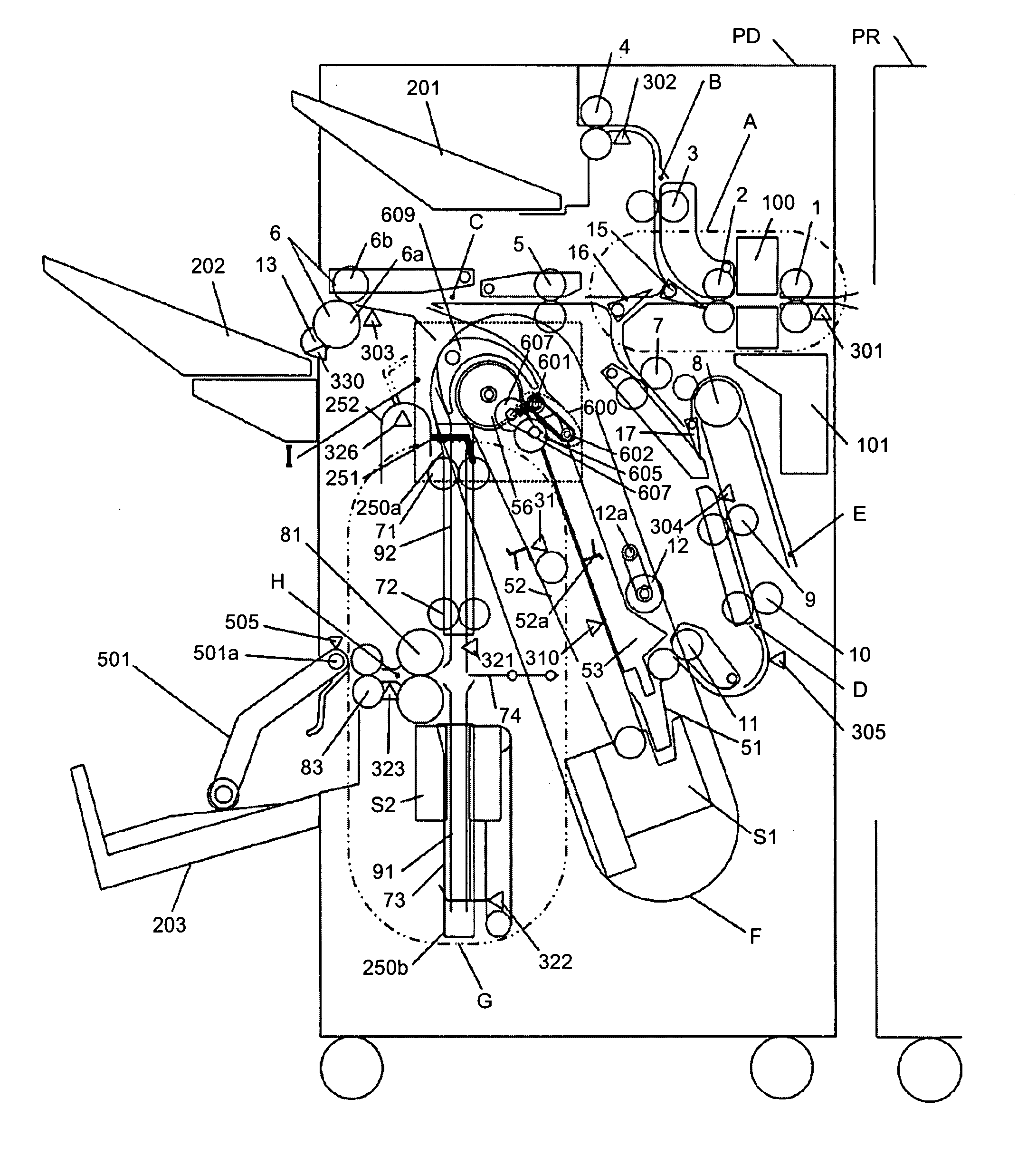
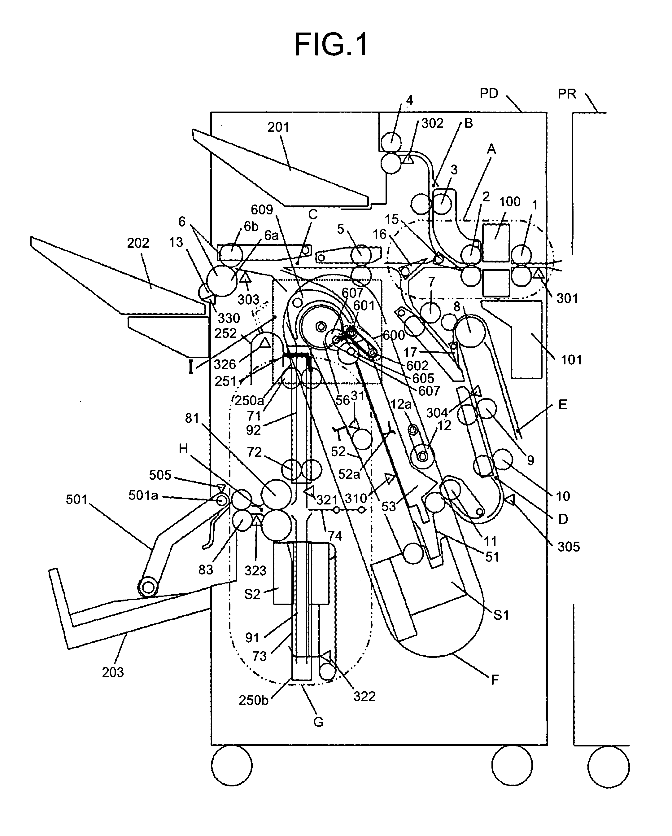
[0069]Like reference characters refer to corresponding parts throughout the drawings, and the same explanation is not repeated. FIG. 1 is a diagram of a system including a sheet processing apparatus and an image forming apparatus according to the present invention. In FIG. 1, the entire sheet processing apparatus and a part of the image forming apparatus are shown.

[0070]In FIG. 1, a sheet processing apparatus PD is attached to a side of an image forming apparatus PR. Sheet-like recording media (sheets) discharged from the image forming apparatus PR are guided to the sheet processing apparatus PD. The sheets pass through a conveying path A having a post processing unit (a punch unit 100 to punch sheets in the first embodiment), which applies post processing to each sheet, and are divided by a branch pawl 15 and a branch pawl 16 to a conveying path B that guides the sheets to an upper tray 201, a conveying path C that guides the sheets to a shift tray 202, and a conveying path D that ...

second embodiment

[0117]As described above, the driving roller is provided opposed to the conveying roller. Consequently, a sheet processing mechanism that prevents a difference in a frictional force applied to each of sheets of a sheet stack and enables more highly accurate sheet alignment is provided.

[0118]A third embodiment of the present invention is different from the first embodiment in operation control for the roller 601.

[0119]As shown in FIG. 18, when sheets are conveyed into the end-binding processing tray F, a leading end of the sheets conveyed may come into contact with the roller 601 depending on length of the sheets or curl that occurs in the sheets. In that case, when the roller 601 rotates in a direction opposite to a conveying direction of the sheets, the sheets may be buckled as shown in FIG. 19. Therefore, when the leading end of the sheets passes the roller 601 or near the roller 601, the roller 601 is stopped or rotated in the conveying direction to prevent the roller 601 from h...

third embodiment

[0124]FIGS. 26A and 26B are flowcharts of an overall control procedure in the sheet processing apparatus PD according to the

[0125]In FIG. 26A, when a job is started, first, the CPU 360 checks whether center binding processing is performed (step S401). When the center binding processing is performed, the CPU 360 rotates the motor M1 and the cam 605 from the home positions by the predetermined amount to move the roller 601 to the standby position (step S402). The CPU 360 rotates the motor M2 and the turn guide member 609 from the home positions by the predetermined amount to form a turn conveying path (step S403). When sheets enters the end-binding processing tray F (YES at step S404) and a leading end of the sheets reaches the roller 601 or near the roller 601 (YES at step S405), the CPU 360 stops the roller 601 or rotates the roller 601 in the sheet conveying direction (step S406). When a predetermined time has elapsed after the rotation, the CPU 360 rotates the roller 601 in the di...


PUM

PropertyMeasurementUnit
Thicknessaaaaaaaaaa
Forceaaaaaaaaaa
Speedaaaaaaaaaa

Abstract

A sheet processing apparatus includes a first processing unit, a second processing unit, a roller, a guide member, and a conveying unit. The first processing unit applies first processing to a recording medium. The second processing unit applies second processing to the recording medium. The roller has a conveying path to convey the recording medium from the first processing unit to the second processing unit along the outer circumference. The guide member guides the recording medium to the conveying path to lead the recording medium to the second processing unit. The conveying unit applies a conveying force to a stack of recording media at an upstream of the guide member in a recording-medium conveying direction.

Description

CROSS-REFERENCE TO RELATED APPLICATIONS[0001]The present document incorporates by reference the entire contents of Japanese priority documents, 2007-016565 filed in Japan on Jan. 26, 2007, 2006-146980 filed in Japan on May 26, 2006, 2006-107581 filed in Japan on Apr. 10, 2006 and 2006-188161 filed in Japan on Jul. 7, 2006.BACKGROUND OF THE INVENTION[0002]1. Field of the Invention[0003]The present invention relates to a sheet processing apparatus and an image forming apparatus.[0004]2. Description of the Related Art[0005]As a technique concerning the sheet processing apparatus, for example, Japanese Patent Application Laid-Open No. 2003-95506 discloses a technology relating to a sheet processing apparatus that applies predetermined processing to a sheet-like recording medium (sheet). The sheet processing apparatus includes a staple processing tray that applies alignment and staple processing to a sheet stack, a conveying path that directly discharges the sheet stack subjected to the ...

Claims


Application Information

Patent Timeline
IPC IPC(8): B65H39/00B65H39/10B65H33/04
CPCB65H29/52B65H29/58B65H31/3027B65H45/18B65H2801/09B65H2404/14B65H2404/1441B65H2404/612B65H2301/42262
Inventor NAGASAKO, SHUUYATAMURA, MASAHIROSUZUKI, NOBUYOSHIKOBAYASHI, KAZUHIROSATOH, SHOHICHIKUNIEDA, AKIRAMAEDA, HIROSHINOMURA, TOMOICHIHATTORI, HITOSHIHIDAKA, MAKOTOICHIHASHI, ICHIRO
Owner RICOH KK
Why Eureka
Try Eureka