[0005]In the above configuration, a space (
air layer) having a dimension substantially equal to an operating distance on an object side of the focusing lens array needs to be ensured between the focusing lens array and the electro-optical panel. Since the light which is emitted from the electro-optical devices and propagates through the space is diffused, it is difficult to ensure the amount of light incident to the focusing lens array is sufficient among the light emitted from the electro-optical devices (that is, the use efficiency of the light is low). Under such circumferences, an
advantage of the invention is to reduce loss of light emitted from electro-optical devices.
[0006]According to an aspect of the invention, there is provided an electro-optical apparatus including: an electro-optical panel on which a plurality of electro-optical devices are arranged; a focusing lens array which focuses light emitted from the electro-optical devices; an optically transparent spacer which is interposed between the electro-optical panel and the focusing lens array and contacts the electro-optical panel and the focusing lens array; and a frame which has a first facing surface facing a first surface which is a surface of the spacer on the side of the focusing lens array, wherein the first surface contacts the first facing surface.
[0007]According to the electro-optical apparatus of the invention, since the spacer is disposed in a gap between the electro-optical panel and the focusing lens array, it is possible to improve the use efficiency of the light emitted from the electro-optical panel, compared with a configuration in which an
air layer is interposed in the gap between the electro-optical panel and the focusing lens array. In the above configuration, the distance between the electro-optical panel and the focusing lens array, both of which contact the spacer, is defined by the dimension of the spacer in an
optical axis of the electro-optical devices. Accordingly, when the dimension of the spacer is properly selected, it is possible to set the distance between the electro-optical panel and the focusing lens array to a predetermined value in the step of disposing the spacer. When the first surface of the spacer contacts the first facing surface of the frame, the position of the spacer relative to the frame is defined. Since the focusing lens array and the electro-optical panel contact the spacer with the spacer interposed therebetween, the positions of the focusing lens array and the electro-optical panel relative to the frame are defined. Accordingly, according to the invention, it is possible to simply set the positions of the focusing lens array and the electro-optical panel in a direction (a direction perpendicular to the first surface and, hereinafter, referred to as a “Z direction”) of the
optical axis of the focusing lens array to predetermined values with high precision. When error in the dimension of the spacer is smaller than that of the frame, it is possible to provide the electro-optical panel with high precision, compared with a configuration in which the position of the electro-optical panel is defined on the basis of the surface of the frame.
[0008]The electro-optical device is a component in which optical characteristics such as brightness or a transmission factor vary depending on the application of
electric energy (for example, the supply of current or the application of a
voltage). The electro-optical device according to the invention includes a light-emitting device (for example, an
electroluminescence device or a
plasma display device) for emitting light by applying
electric energy and a
light modulation device (for example, a
liquid crystal device or an electrophoretic device) for changing a transmission factor by applying
electric energy.
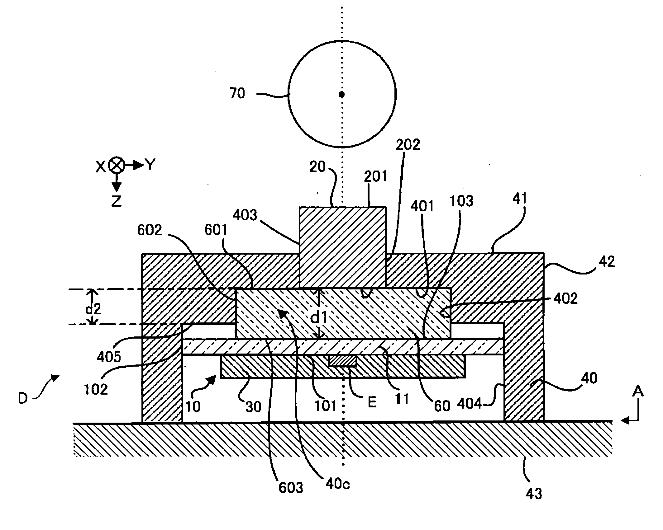
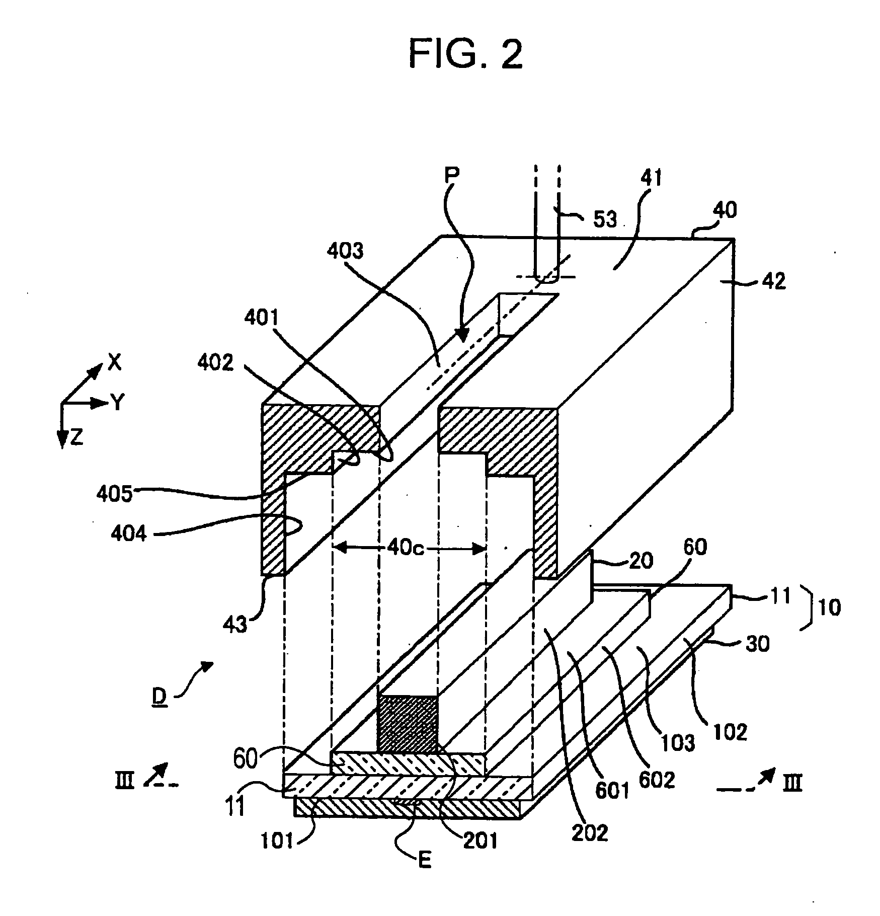
[0009]In a suitable aspect of the invention, a recess (for example, a recess 40c) having the first facing surface as a bottom is formed in the frame and the spacer is inserted into the recess. In this state, the spacer is disposed such that the second surface opposite to the first surface protrudes from the recess to the electro-optical panel. That is, the distance from the first facing surface to the surface (for example, the surface 405) of the frame on the side of the electro-optical panel (the depth of the recess) is set to be smaller than the thickness of the spacer. In other words, when viewed from the electro-optical panel, the surface of the frame on the electro-optical panel is positioned at the inside of the second surface of the spacer. Accordingly, the electro-optical panel contacts only the second surface of the spacer so as not to contact the surface of the frame on the side of the electro-optical panel. By this configuration, it is possible to set the position of the electro-optical panel by only the thickness of the spacer with high precision.
[0010]The depth of the recess may be substantially equal to or larger than the thickness of the spacer. In this configuration, the electro-optical panel contacts both the second surface of the spacer and the surface of the frame on the side of the electro-optical panel or only the surface of the frame on the side of the electro-optical panel. Accordingly, the position of the electro-optical panel relative to the focusing lens array is defined by the position of the surface of the frame on the electro-optical panel. According to this aspect, it is possible to simply dispose the electro-optical panel at a predetermined position with high precision by properly selecting the position of the surface of the frame on the electro-optical panel.

