Projection lens unit
a technology of projection lens and projection lens, which is applied in the direction of mountings, instruments, optics, etc., can solve the problems of degrading the quality of the image projected onto the screen, degrading the focal point of the projection lens system, and not achieving the desired amount of movemen
- Summary
- Abstract
- Description
- Claims
- Application Information
AI Technical Summary
Benefits of technology
Problems solved by technology
Method used
Image
Examples
first embodiment
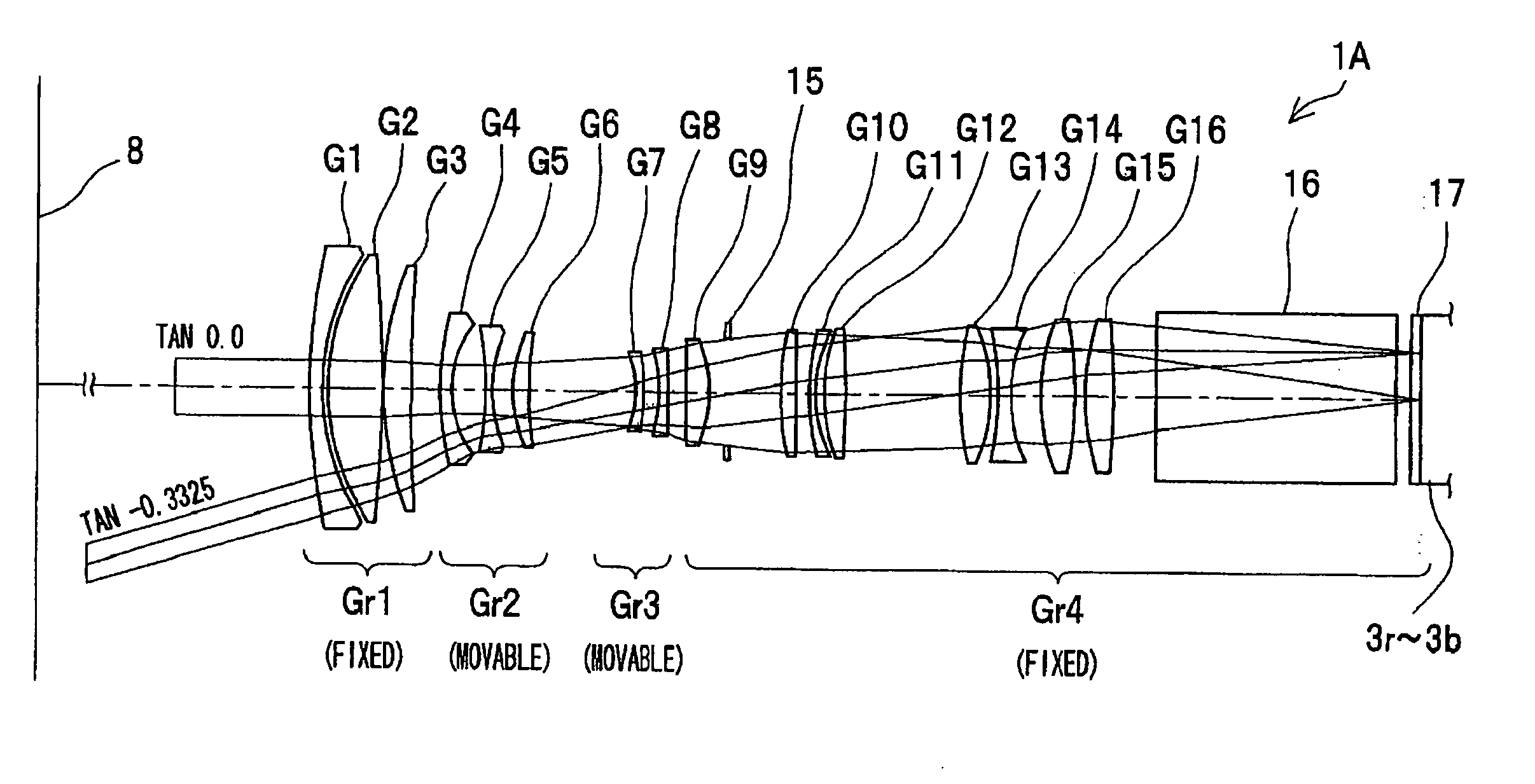
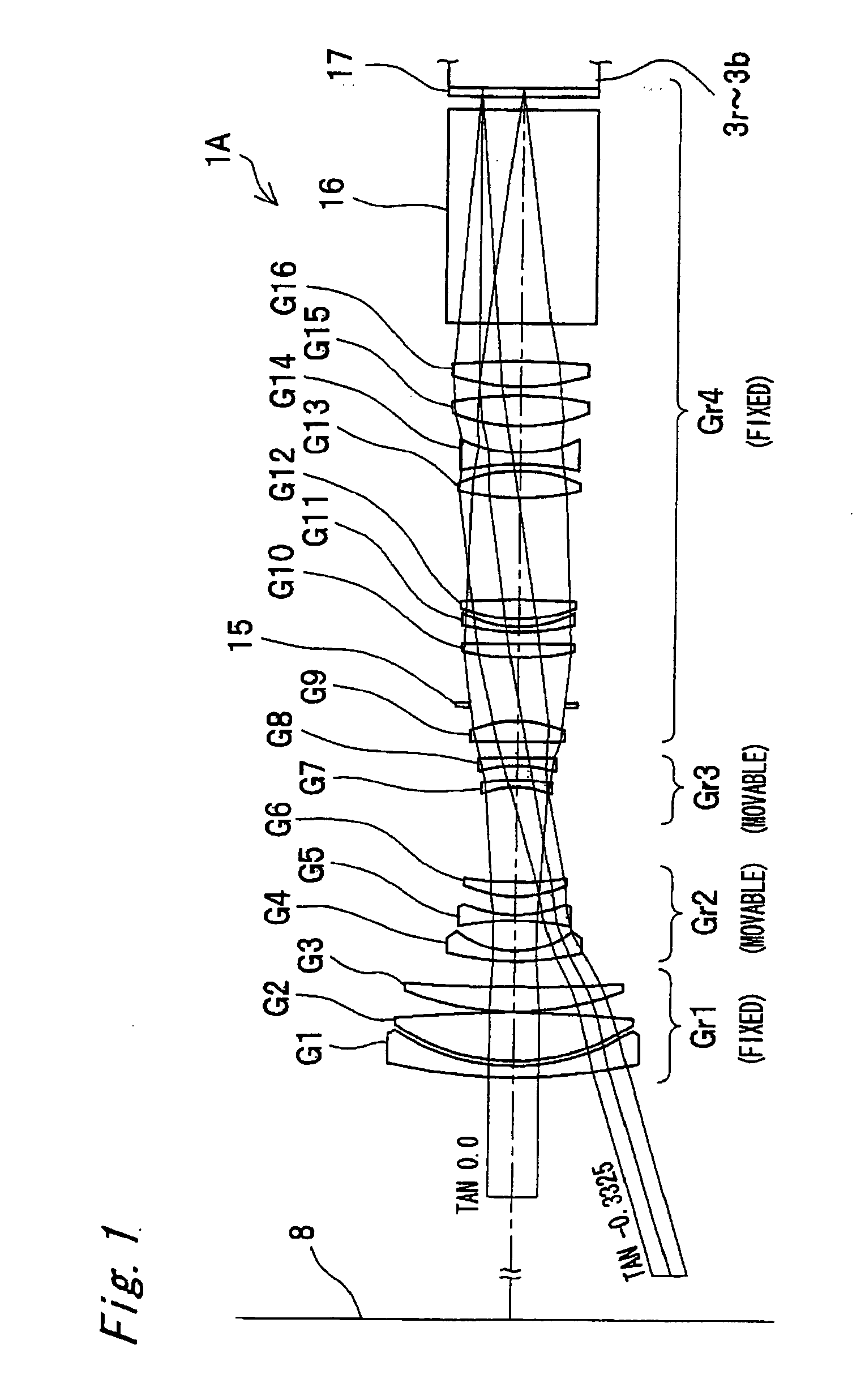
[0041]FIG. 1 shows the projection lens system 1A of a first aspect of the invention. This projection lens system 1A forms a portion of a front-projection type projector 2, shown in FIG. 4 through FIG. 6. A projection lens unit comprises the projection lens system 1A, and lens barrels, described below, which hold the lenses G1 to G16 of the projection lens system 1A (a fixed lens barrel 21, main lens barrel 22, and movable lens barrel 25). In addition to the projection lens system 1A, the projector 2 comprises, as a reflection-type image formation device, DMDs 3r, 3g, 3b, a light source 4, an illumination optical system 5, a color separation / combination prism 6, a total internal reflection prism 7, and a screen 8 (see FIG. 1).
[0042] In this aspect, the light source 4 comprises for examine a light emission tube 11 which is a xenon lamp, and an elliptical reflector 12. The illumination optical system 5 comprises a rod integrator 13 and a relay lens group 14; light emitted from the lig...
second embodiment
[0078]FIG. 17 and FIG. 18 show the projection lens system 1B of a second aspect of the invention. This projection lens system 1B forms a portion of a projector 2, similarly to the case of the first aspect, and similarly to the first aspect comprises a light source 4, illumination optical system 5, color separation / combination prism 6, total internal reflection prism 7, and screen 8 (see FIG. 4 to FIG. 6).
[0079] The projection lens system 1B comprises 16 lenses G1 to G16 and a diaphragm 15, and has telecentric properties. The radii of curvature of the lenses G1 to G16, the distances on the optical axis between the lens surfaces r1 to r39 of the lenses G1 to G16, the refractive indices N1 to N20, and the Abbe numbers v1 to v20, are as indicated in Table 5 and Table 6 below.
TABLE 5DISTANCE BETWEENRADIUS OFSURFACES ONABBEOPTICAL ELEMENTCURVATUREOPTICAL AXISREFRACTIVE INDEXNUMBERLENS G1r1: 99.180—d1: 11.431N1: 1.58913ν1: 61.25r2: 11824.525d2: 1.851LENS G2r3: 108.956(ANOMALOUSd3: 4.196...
third embodiment
[0089]FIG. 21 shows the projection lens system 1C of a third aspect of the invention. This projection lens system 1C forms a portion of a projector 2, similarly to the case of the first aspect, and similarly to the first aspect comprises a light source 4, illumination optical system 5, color separation / combination prism 6, total internal reflection prism 7, and screen 8 (see FIG. 4 to FIG. 6).
[0090] The projection lens system 1C comprises 17 lenses G1 to G17 and a diaphragm 15, and has telecentric properties. The radii of curvature of the lenses G1 to G17, the distances on the optical axis between the lens surfaces r1 to r39 of the lenses G1 to G17, the refractive indices N1 to N19, and the Abbe numbers v1 to v19, are as indicated in Table 7 and Table 8 below.
TABLE 7DISTANCE BETWEENRADIUS OFSURFACES ONABBEOPTICAL ELEMENTCURVATUREOPTICAL AXISREFRACTIVE INDEXNUMBERLENS G1r1: 249.283—d1: 5.000N1: 1.64769ν1: 33.84r2: 108.596d2: 2.324LENS G2r3: 111.490d3: 11.725N2: 1.60311ν2: 60.69r4:...
PUM
 Abstract
Description
Claims
Application Information
 - R&D
- Intellectual Property
- Life Sciences
- Materials
- Tech Scout
- Unparalleled Data Quality
- Higher Quality Content
- 60% Fewer Hallucinations
Browse by: Latest US Patents, China's latest patents, Technical Efficacy Thesaurus, Application Domain, Technology Topic, Popular Technical Reports.
© 2025 PatSnap. All rights reserved.Legal|Privacy policy|Modern Slavery Act Transparency Statement|Sitemap|About US| Contact US: help@patsnap.com


