Light-emitting module installing thermo-electric controller

a technology of thermo-electric controller and light-emitting module, which is applied in the direction of lasers, laser cooling arrangements, laser details, etc., can solve the problems of excessive cooling or excessive heating of ld, and avoiding the influence of heat radiated from the cap ceiling. , to achieve the effect of improving focusing efficiency

Active Publication Date: 2007-10-11
SUMITOMO ELECTRIC IND LTD
View PDF6 Cites 21 Cited by
  • Summary
  • Abstract
  • Description
  • Claims
  • Application Information

AI Technical Summary

Benefits of technology

[0015] According to another aspect, a base may include a first portion and a second portion. The first portion may be virtually rectangular and mount a laser diode on one of its sides and a thermistor on another side. Further, the second portion may be attached to another side of the first portion and an opening may be provided in the second portion so as to expose the thermistor mounted on the second surface in this opening. The side wall of the opening may function as an overhung portion so as to shield the heat radiated from the cap.
[0016] According to another aspect, a light-emitting module may include a carrier, a laser diode may be mounted on one surface of the carrier, a thermistor may be mounted on another surface of the carrier and the other surface may be attached to a base. A hollow may be formed on the surface of the base where the carrier is attached and the hollow may receive the thermistor mounted on the other surface of the carrier. The side wall of the base where the hollow is formed may shield the heat radiated from the carrier.
[0017] According to another aspect of the light-emitting module of the invention is that, a supporting portion and a depressed portion may be formed on the ceiling of a cap and the supporting portion may protrude into a space formed by the cap and a stem while the depressed portion may protrude toward the outside of a package with respect to the space. The thermistor may be mounted on a side of a base in a position facing the depressed portion of the cap. In a case that a lens, focusing light output from a laser diode, is mounted on the supporting portion of the cap, the spacing between the thermistor mounted on the base and the ceiling of the cap is not shortened by the depressed portion of the ceiling although the spacing between the lens and the semiconductor laser is reduced to improve the focusing efficiency. Accordingly, the influence of the heat radiated from the cap ceiling may be avoided.

Problems solved by technology

The thermistor is thus influenced by the temperature outside the package (radiation from the case wall surface) thus resulting in an error in the temperature measurement of the LD.
A thermo-electric cooler that mounts the LD cools or heats the LD based on the temperature measured by the thermistor so that an error in the temperature measurement leads to excessive cooling or excessive heating.
Thus, the LD is excessively cooled or heated to T-Δ[° C.] by the thermoelectric cooler.
Thus, it is difficult to accurately control the temperature of the LD to a predetermined value.
In particular, this problem is critical in a case, when an optical transmitter is used for optical communications of DWDM (Dense Wavelength Division Multiplexing).
However, this approach results in an increased size of a peripheral circuit of the optical transmitter.
A heat-shielding member described in US 2003-043868A covers the LD and other elements to be cooled at the same time although it is difficult to provide such members within a coaxial type package.
More specifically, the coaxial type package has a structure where a case supports a lens so that the spacing between the LD and the case is extremely small, accordingly, it is difficult to provide a heat-shielding member described in U.S. Pat. No. 6,856,475.

Method used


Image

  • Light-emitting module installing thermo-electric controller
  • Light-emitting module installing thermo-electric controller
  • Light-emitting module installing thermo-electric controller

Examples


first embodiment

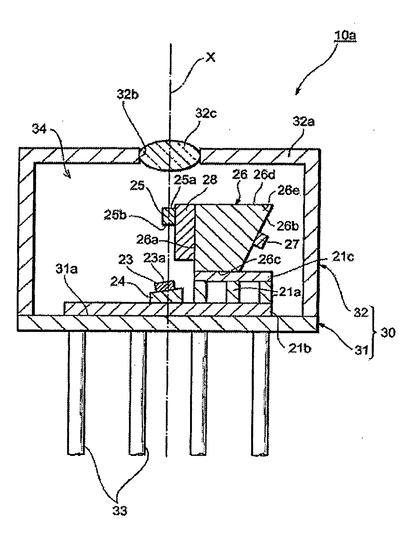
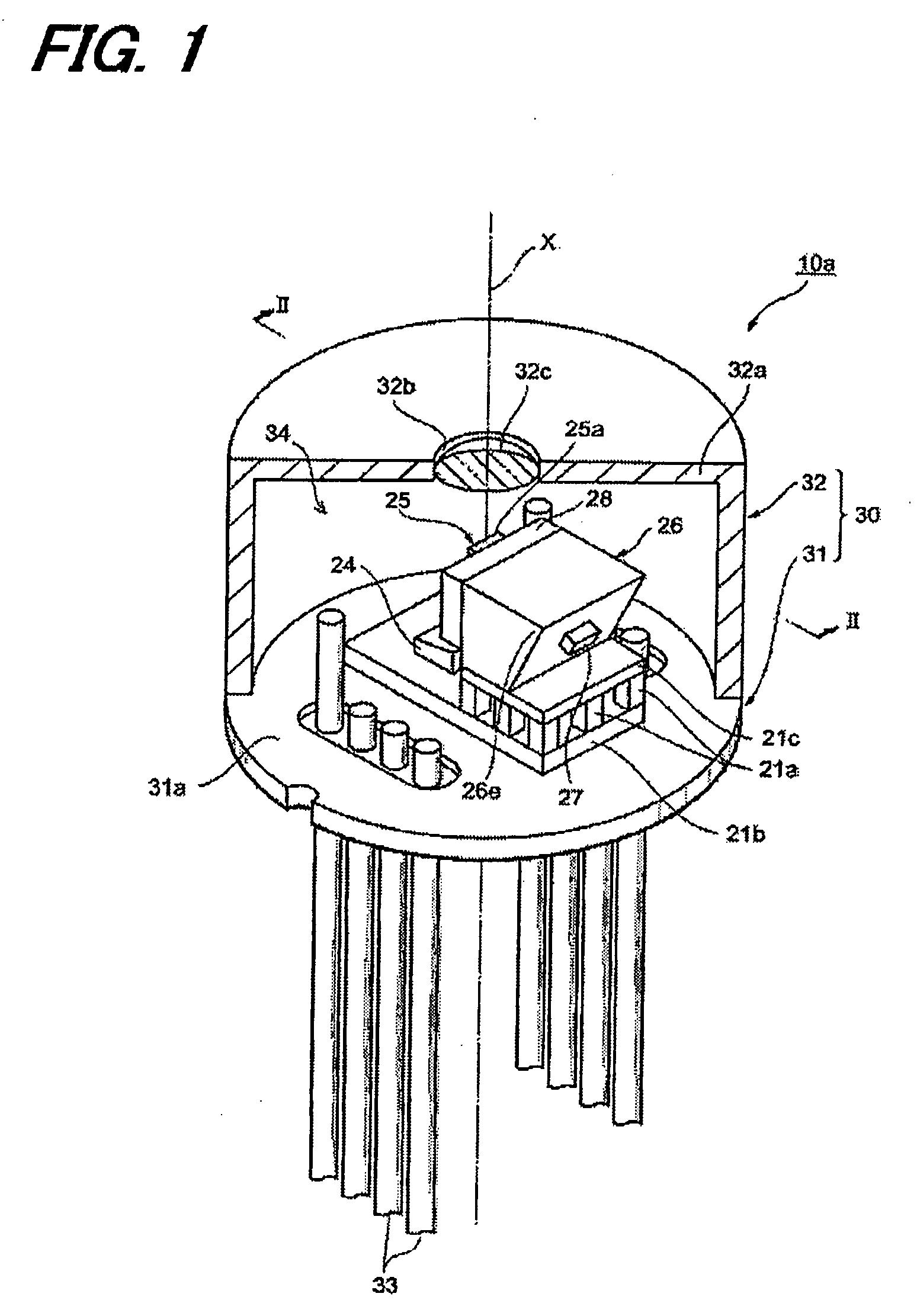
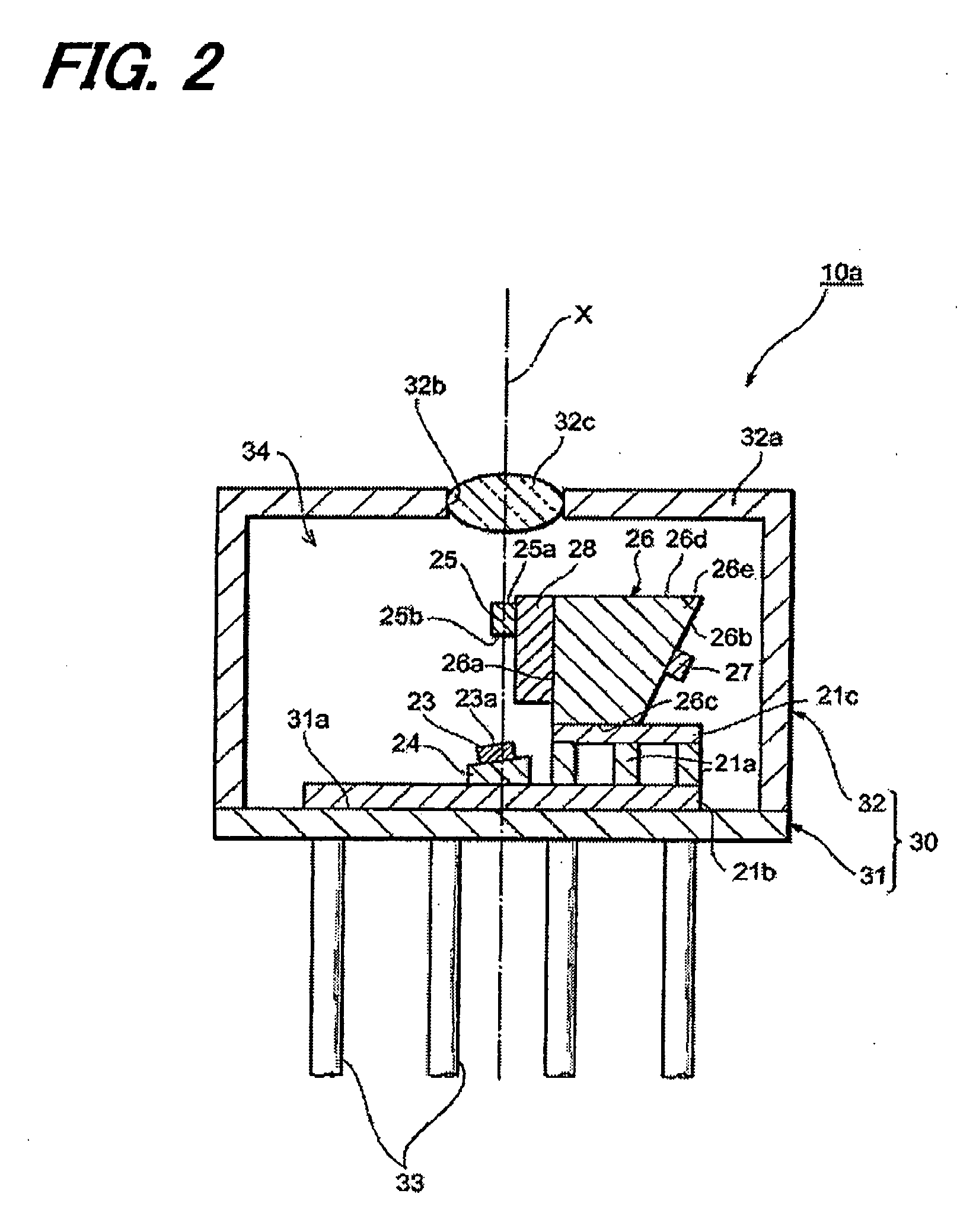
[0032]FIG. 1 is a partial broken perspective view of a light-emitting module 10a according to a first embodiment of the invention. FIG. 2 is a cross-sectional view of the light-emitting module 10a taken along the line II-II in FIG. 1. The light-emitting module 10a is a coaxial type and includes a can package 30 housing electronic components such as a semiconductor laser diode (hereinafter referred to as an LD).

[0033] The can package 30 includes a stem 31 and a cap 32. The stem 31 is disk-shaped and a primary surface 31a of the stem 31 is orthogonal to the center axis x of the can package 30. Electronic components such as the LD are mounted on the primary surface 31a of the stem 31. A plurality of lead terminals 33 is extended from the stem 31. These lead terminals 33 pass the stem 31 in parallel to the center axis x.

[0034] The cap 32 is a cylindrical component having a ceiling 32a. A lens 32c, focusing the light from the LD, is fitted in an opening 32b provided at the ceiling 32a....

second embodiment

[0047]FIG. 5 is a partial broken view of a light-emitting module 10c according to the second embodiment. FIG. 6 is an exploded view of the base 116 mounted on the light-emitting module 10c. The base 226 according to present embodiment includes a first portion 226a and a second portion 226b. The first portion 226a has a surface 226c that mounts an LD carrier 28 and its opposite surface 226d. The second portion 226b has a surface 226e facing the surface 226d of the first portion 226a and its opposite surface 226f. The surface 226d of the first portion 226a is attached to the surface 226e of the second portion 226d.

[0048] Near the center of the surface 226f of the second portion 226b, an opening 226g is formed such as to pass the second portion 226b. The surface 226d of the first portion 226a is exposed in the opening 226g. The thermistor 27 is mounted approximately at the center of the interior of the opening 226g. The inner wall 226j of the opening 226g thermally shields the thermis...

third embodiment

[0054]FIG. 9 is a partial broken view of a light-emitting module 10d according to the third embodiment. A light-emitting module 10d according to this embodiment has a base 426 and an LD carrier 428. FIG. 16 is an enlarged view of the base 426 and the LD carrier 428. The base 426 is made of metal such as CuW and has a rectangular shape. The surface 426a of the base 426 mounts an LD carrier 428 and an LD 25 is mounted on the LD carrier 428. The surface 426a includes a hollow 426g with a rectangular shape. As shown in FIG. 10, the LD carrier 428 mounts the thermistor 27 on a second surface 428b opposite to the first surface 428a of the LD carrier 428 that mounts the LD 25. The carrier 428 may be made of an insulating material with good thermal conductivity. For example, aluminum nitride (AlN) is an appropriate material. The thickness of the carrier 428 is about 0.2 mm.

[0055] The LD 25 is mounted on the first surface 428a of the LD carrier 428 so that the light-emitting surface 25a and...


PUM


Abstract

There is provided a light-emitting module which suppresses wavelength drift. A light-emitting module according to the invention includes a stem and a cap fixed to the upper surface of the stem. A thermo-electric cooler is mounted on the stem and a base is mounted on the thermo-electric cooler. A laser diode is mounted on one side of the base. A thermistor that measures the temperature of the laser diode is mounted on another side. The other side includes an overhung portion that blocks radiant heat transmitting from the cap toward the thermistor.

Description

[0001] This application is based on and claims the benefit of priority from the prior Japanese Patent Application No. 2006-085528, filed on Mar. 27, 200 and No. 2006-150484, filed on May 30, 2006, the entire contents of which are hereby incorporated by reference. BACKGROUND OF THE INVENTION [0002] 1. Technical Field [0003] The present invention relates to a light-emitting module. [0004] 2. Background Art [0005] The package of an optical transmitter including a semiconductor laser element has two types as follows: [0006] One is a so-called butterfly type package disclosed in U.S. Pat. No. 6,856,475. The other is a so-called coaxial type package disclosed in U.S. Appl. Pub, No. 2004-245446A and 2003-043868A. [0007] The laser module described in U.S. Pat. No. 6,856,475 comprises a butterfly type package, a base accommodated in the package, a thermo-electric cooler arranged between the package and the base, and a device to be controlled in temperatures such as a laser diode, a lens or a...

Claims


Application Information

Patent Timeline
Patent Type & Authority Applications(United States)
IPC IPC(8): H01S3/04H01S5/02315
CPCH01S5/02212H01S5/02236H01S5/0683H01S5/02415H01S5/06804H01S5/02288H01S5/023H01S5/0233H01S5/0235H01S5/02253H01S5/02315
Inventor OOMORI, HIROTAKA
Owner SUMITOMO ELECTRIC IND LTD
Why Eureka
Try Eureka