

Twist drill
- Summary
- Abstract
- Description
- Claims
- Application Information
AI Technical Summary
Benefits of technology
Problems solved by technology
Method used
Image

Examples
Embodiment Construction
[0022] Parts that correspond to one another in all the figures are identified by the same reference numbers.
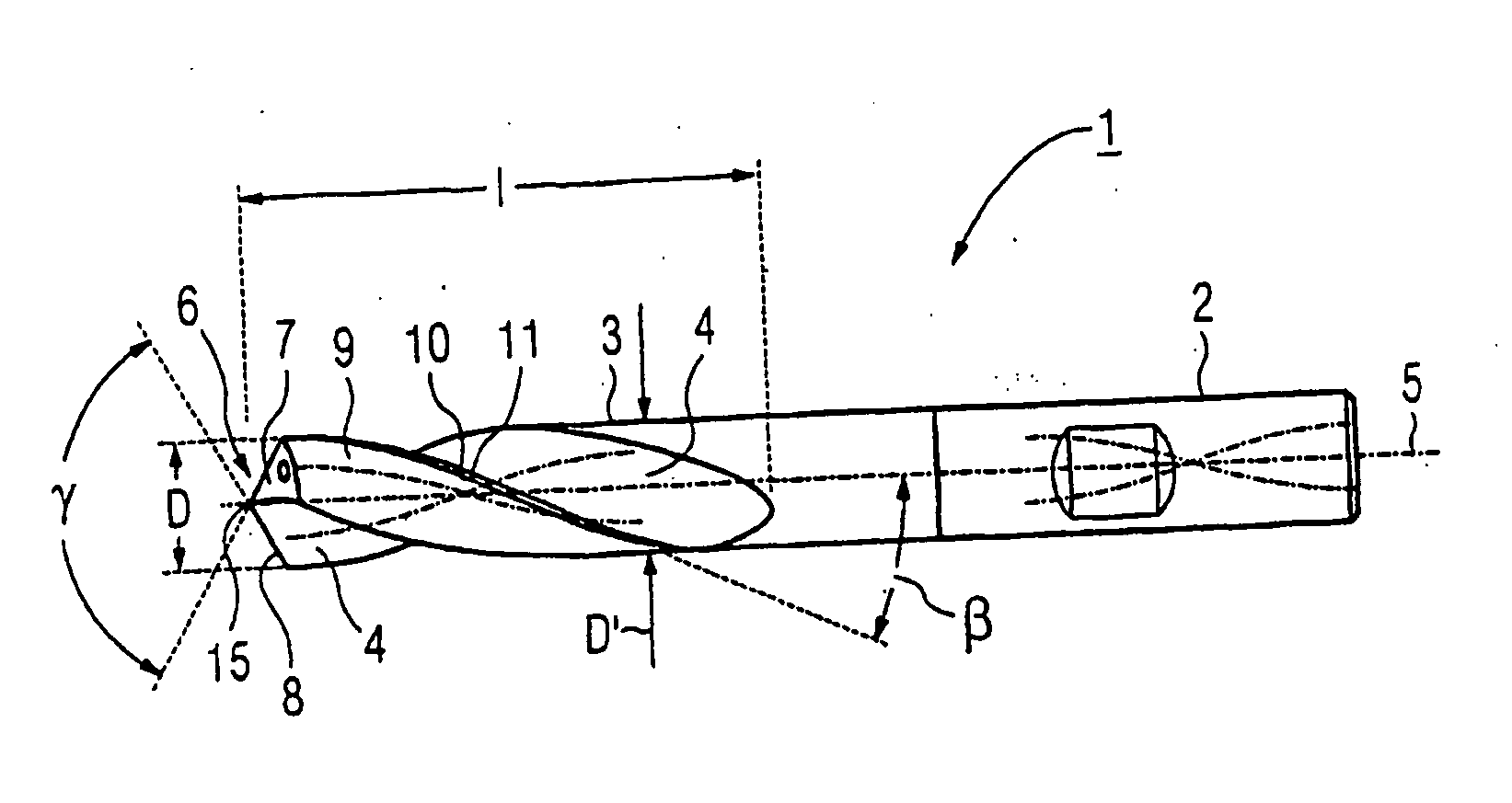
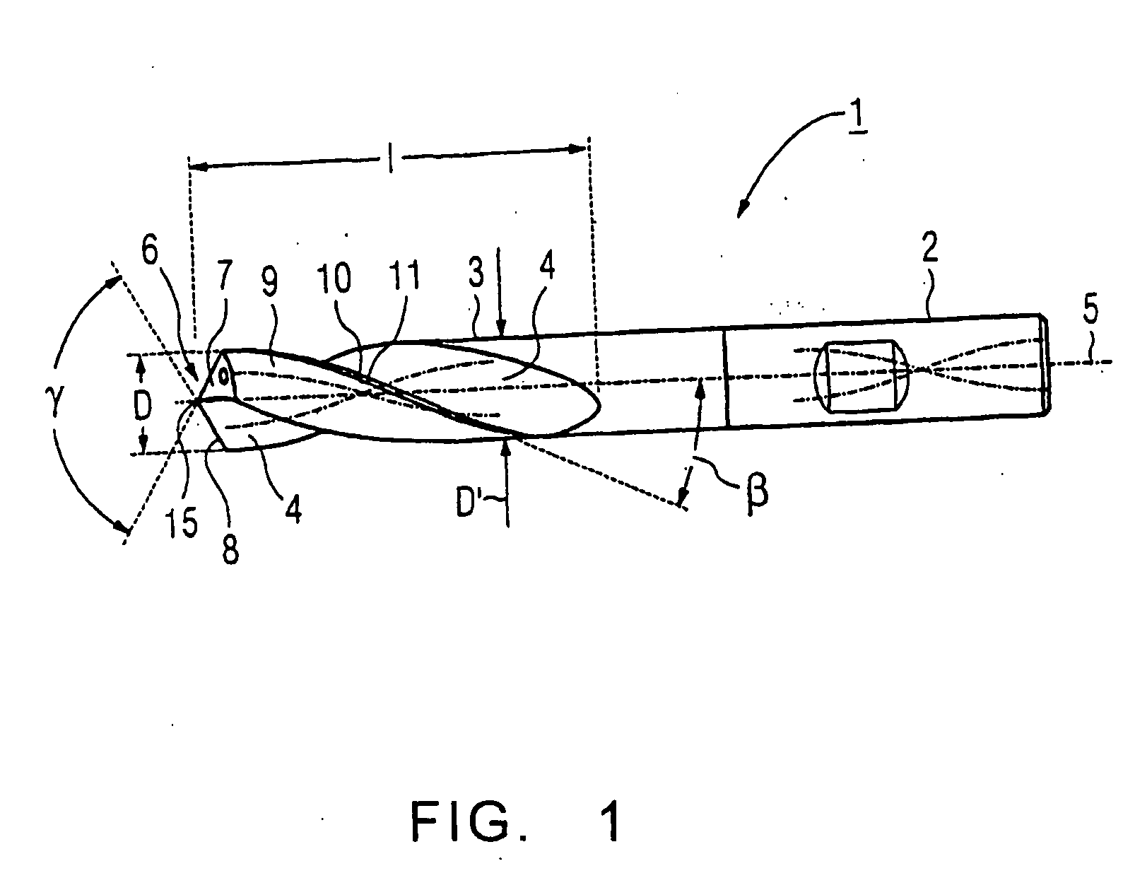
[0023]FIG. 1 shows a twist droll 1 with an essentially cylindrical base body which has a shaft 2 and a cutting part 3 with a cutting part length 1. In the cylindrical surface of the droll 1 or its cutting part 3, there are two chip flutes 4 that are diametrically opposite each other. The chip flutes 4 extend in a spiral fashion around the center axis 5 of the droll 1 and emerge in the end surface of the droll 1 which forms the drill tip 6. The center longitudinal axis 5 of the droll 1 is simultaneously its axis of rotation, around which the droll 1 can be rotated during its use.
[0024] The twist droll 1 also has two primary clearance faces 7 and two primary cutting faces 8, as well as two secondary clearance faces 9, each of which has a circular land 10 and a secondary cutting face 11. The spiral or twist angle β is preferably (30±3)°, advantageously 30°, or (40±3)°, advantag...
PUM
| Property | Measurement | Unit |
|---|---|---|
| Length | aaaaa | aaaaa |
| Length | aaaaa | aaaaa |
| Fraction | aaaaa | aaaaa |
Abstract
Description
Claims
Application Information