Check patentability & draft patents in minutes with Patsnap Eureka AI!

Two platen traverse cylinder mounting system

Inactive Publication Date: 2007-10-11
BUHLERPRINCE
View PDF22 Cites 12 Cited by
  • Summary
  • Abstract
  • Description
  • Claims
  • Application Information

AI Technical Summary

Benefits of technology

[0010]In both embodiments, the positioning of the traverse cylinder(s) behind the movable platen allows dies to be changed and facilitates the replacement or repair of the dies. With such a system, a relatively large die cast machine capable of operation in the 3000 to 4000 ton range can be relatively quickly opened and closed using one or more traverse cylinders which do not interfere with the placement of dies. These and other features, objects and advantages of the present invention will become apparent upon reading the following description thereof together with reference to the accompanying drawings.

Problems solved by technology

The die casting of such parts utilizing metal alloys requires larger and more complex dies and tooling than conventional injection molding.
Thus, die casting machine designs are more restrictive than injection molding machines in that the space between the platens preferably is unoccupied.
The contraction of aluminum during solidification after injection of the molten material in such die cast machines requires relatively high forces to open the machine for removing the casting from the die.
Also, more complicated tooling requires higher closing forces to lock the various die cores and slides into position.
This removes the cylinders from the die space, however, large forces generated from the rapid opening and closing of the somewhat massive moving platen produces large forces and bending moments at the connection between the cantilevered pedestal and the base, which can, as a result, be subject to failure.
This results in an undesirable increase in the duty cycle of operation.
Also, the traverse cylinders undesirably extend within the die space and a less than desirable balance of opening and closing forces are exerted by the traverse cylinders.

Method used


Image

  • Two platen traverse cylinder mounting system
  • Two platen traverse cylinder mounting system
  • Two platen traverse cylinder mounting system

Examples


Embodiment Construction

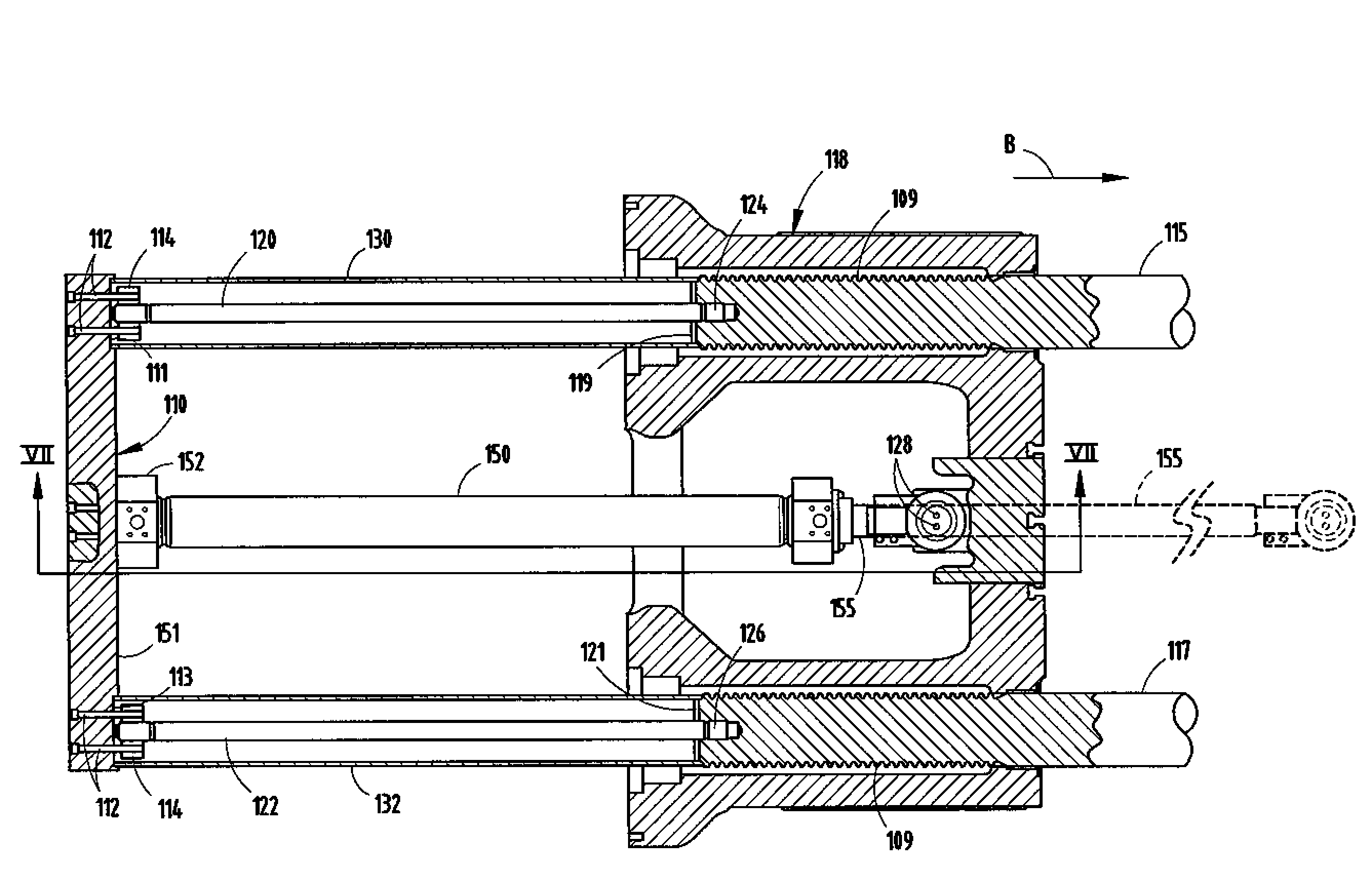
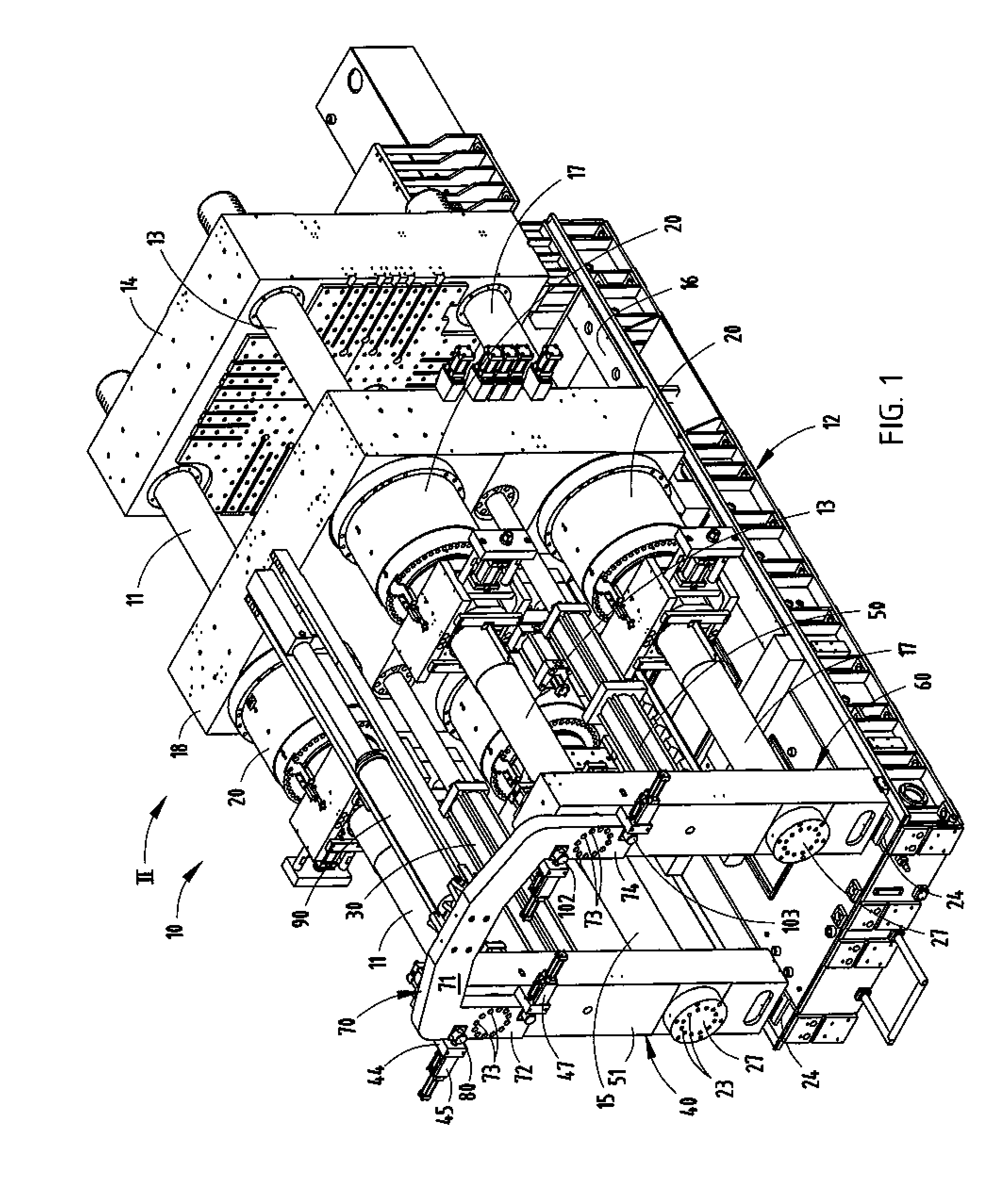
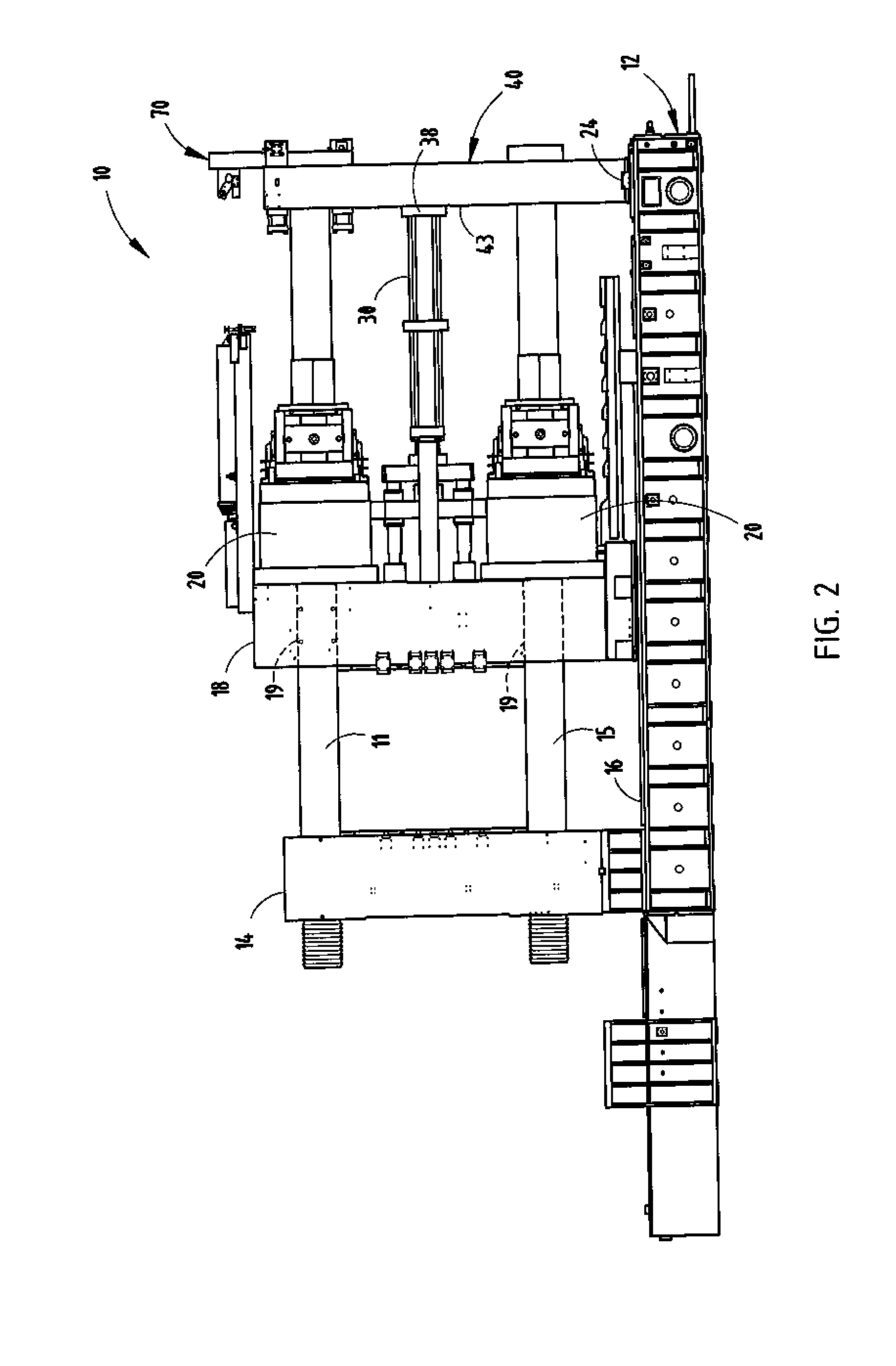
[0019]The die cast machine 10 of the present invention is shown in FIGS. 1 and 2 and includes a frame 12 on which there is mounted a fixed platen 14 and movably mounted on rails 16 is a movable platen 18. Platens 14 and 18 are coupled by four tie bars, including upper tie bars 11 and 13 and lower tie bars 15 and 17. One end of each of the tie bars is mounted to the fixed platen 14 in a conventional manner and movably coupled to the movable platen 18 through apertures 19 (FIG. 2) in platen 18 by means of four substantially identical threaded locking mechanisms 20 which engage the threaded ends of the tie bars 11, 13, 15, and 17 when platen 18 is in a closed position, allowing four substantially identical pressure cylinders associated with locking mechanism 20 to apply lock-up pressure to the movable platen and dies contained between the fixed and movable platens, respectively.

[0020]Machine 10 can generally be of the type shown in U.S. Patent Publication 2003 / 0217829 with respect to t...


PUM


Abstract

A mounting system for one or more traverse cylinders of a die cast machine positions the cylinders behind the movable platen on a side out of the die area between the platens. A horizontally extending cylinder support bar is mounted between the ends of the lower tie bars. A traverse cylinder is mounted between the support bar and movable platen. In another embodiment, vertically extending cylinder support bars are mounted to the lower and upper tie bars on each side of the machine, with the lower ends being fixedly secured to the lower tie bars and the upper ends detachably secured to the upper tie bars. The traverse cylinders are mounted between the support bars and the movable platen.

Description

CROSS-REFERENCE TO RELATED APPLICATIONS[0001]This application claims priority under 35 U.S.C. § 119(e) on U.S. Provisional Application No. 60 / 790,641 entitled Two PLATEN TRAVERSE CYLINDER MOUNTING SYSTEM, filed on Apr. 10, 2006, by Rodger W. Brower, et al. and U.S. Provisional Application No. 60 / 791,356 entitled Two PLATEN TRAVERSE CYLINDER MOUNTING SYSTEM, filed on Apr. 12, 2006, by Frank D. R. Baron, et al., the entire disclosures of which are incorporated herein by reference.BACKGROUND OF THE INVENTION[0002]The present invention relates to a mounting system for a traverse cylinder in a die cast machine.[0003]Two platen die cast machines are used for the die casting of relatively large parts from molten metal alloys. The die casting of such parts utilizing metal alloys requires larger and more complex dies and tooling than conventional injection molding. The space between the platens of such die cast machines and the tie bars coupling the platens together preferably is free of obs...

Claims


Application Information

Patent Timeline
IPC IPC(8): B28B7/00
CPCB29C45/6728B22D17/266
Inventor BARON, FRANK D. R.BROWER, RODGER W.HEGEL, ROBERT W.HAUSER, DANIELLUCHETTI, MARCO
Owner BUHLERPRINCE
Features
  • R&D
  • Intellectual Property
  • Life Sciences
  • Materials
  • Tech Scout
  • Unparalleled Data Quality
  • Higher Quality Content
  • 60% Fewer Hallucinations
Learn More