
Implant, device and method for determining a position of the implant in a body

a technology of implants and body parts, applied in the field of implants, can solve the problems of catheter removal, catheter removal from the vessel, and the inability to localize radiographicly the position of stents, etc., and achieve the effect of simple and precise determination of the position of implants in the body

Active Publication Date: 2007-10-11
SIEMENS HEALTHCARE GMBH
View PDF13 Cites 106 Cited by
  • Summary
  • Abstract
  • Description
  • Claims
  • Application Information

AI Technical Summary

Benefits of technology

[0010] The object of the invention is to overcome the disadvantages of the prior art. In particular an implant, a device and also a method for determining the position of an implant in a body is to be provided, which make it possible especially easily and precisely to determine the position of the implant in the body.

Problems solved by technology

One disadvantage of this method is that the position of stents which cannot be localized radiographically after removal of the catheter or of the guide wire can no longer be determined.
A disadvantage of this method is that the catheter used for ultrasound imaging has to be removed from the vessel before the stent is inserted.
A disadvantage is that the measurement device used for this must be arranged in a screening chamber.
This significantly restricts the handling capabilities of the catheter.
A disadvantage of the known device is that the catheter can only be employed in few special medical applications.
Furthermore the accuracy of the position determination is very badly affected by metallic objects located in the vicinity of the end area.

Method used


Image

  • Implant, device and method for determining a position of the implant in a body
  • Implant, device and method for determining a position of the implant in a body
  • Implant, device and method for determining a position of the implant in a body

Examples


Embodiment Construction

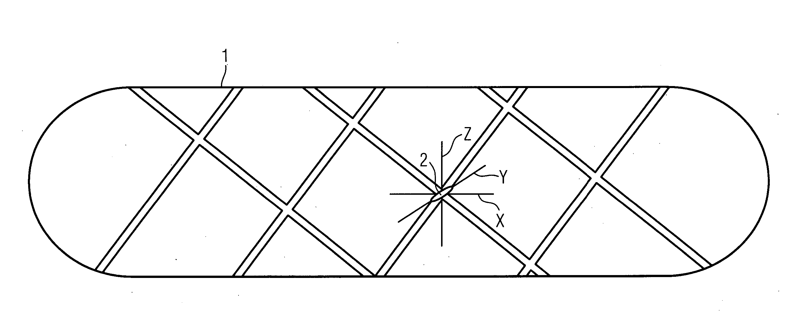
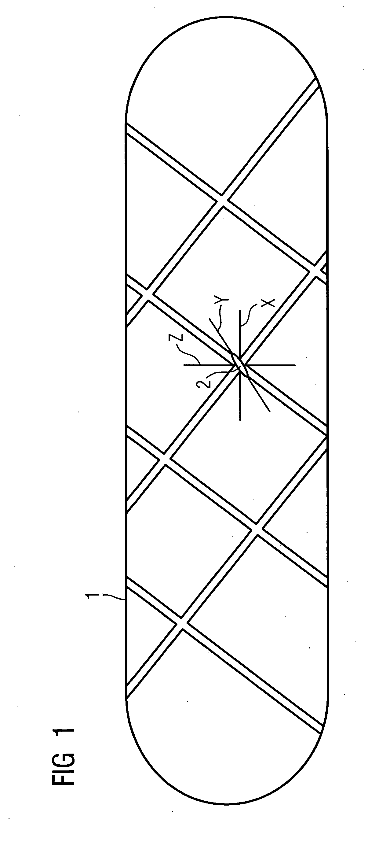
[0057]FIG. 1 shows a stent 1 with a transponder 2 fitted to it, X, Y, Z, indicate an X-, Y- and Z direction of transmit and / or receive antennas of the transponder 2 not shown in the diagram.

[0058] The stent 1 is embodied in the form of a tubular mesh. The mesh is constructed from a base material, such as stainless steel, Lithinol or other materials usual for stents 1. The mesh can be provided with a coating. The coating can be intended to protect the mesh and / or have a suitable substance for preventing restenoses of a vessel. The transponder 2 is fitted to the mesh of the stent 1. The transponder 2 features transmit and / or receive antennas not shown in the diagram for transmitting and / or receiving signals to / from of the X-, Y- and Z directions at right angles to each other. There can essentially be any number of transmit or receive directions. For example the Y direction can represent a receive direction and the X direction as well as the Z direction a transmit direction. The trans...


PUM


Abstract

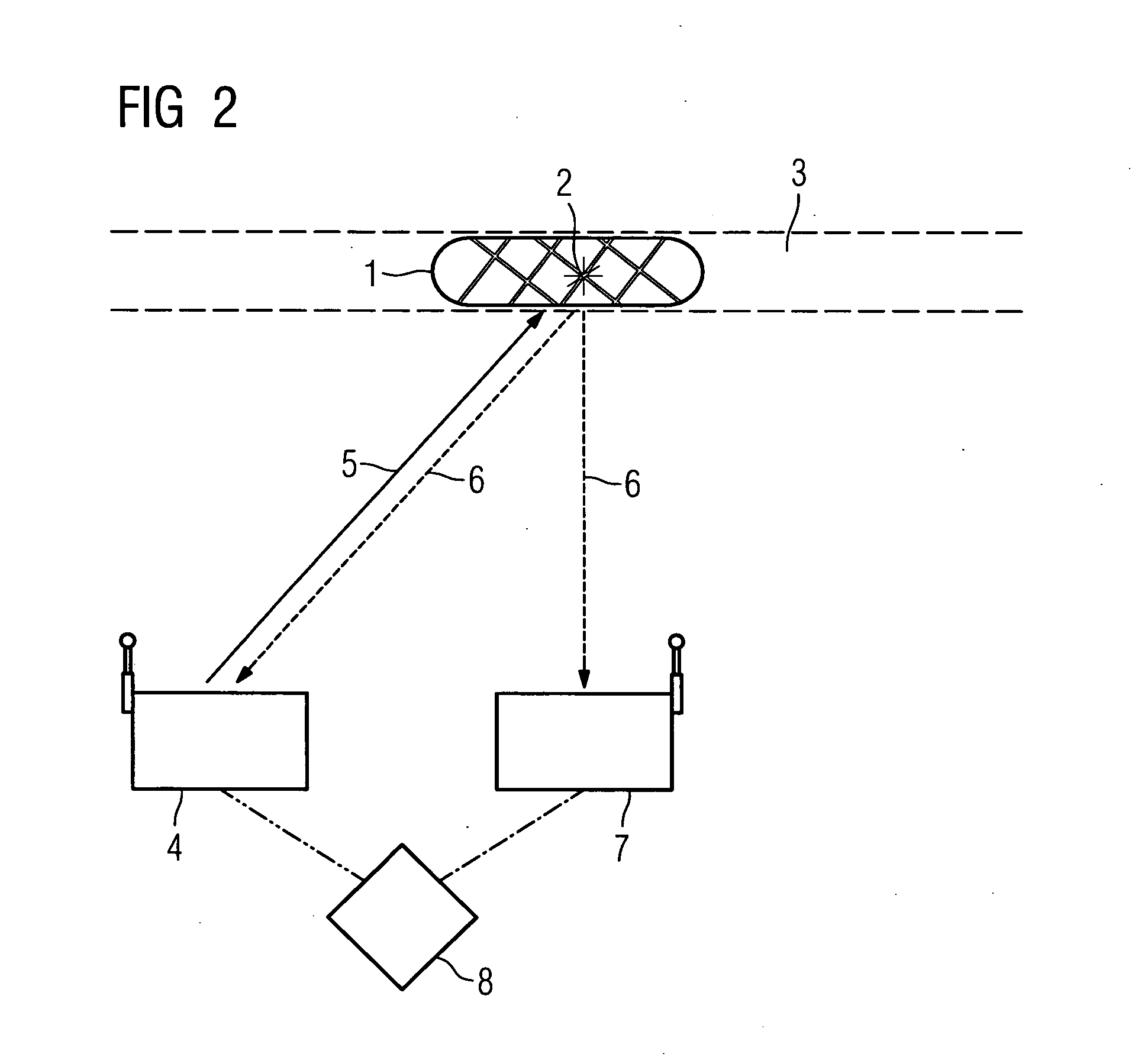
the invention relates to an implant, a method and a device for determining the position of the implant. To improve the accuracy of determining the position it is proposed to provide a transponder on the implant suitable for determining the position.

Description

CROSS REFERENCE TO RELATED APPLICATIONS [0001] This application claims priority of German application No. 10 2005 034 167.5 filed Jul. 21, 2005, which is incorporated by reference herein in its entirety. FIELD OF THE INVENTION [0002] The invention relates to an implant as well as to a device and a method for determining a position of the implant in a body. BACKGROUND OF THE INVENTION [0003] An implant for insertion into the body is known from DE 299 24 228 U1. The implant concerned is a stent for prophylaxy of a restenosis of a vessel. In general stents are inserted into hollow vessels, such as blood vessels or body openings for example, in order to open these out and keep them in their expanded state. Usually catheters and guide wires are employed to insert the stent. [0004] In coronary angiography the localization of the stent with reference to x-ray images of the body tissue is also known. Stents which are manufactured from materials with a low x-ray absorption sometimes cannot b...

Claims


Application Information

Patent Timeline
IPC IPC(8): A61B5/05A61F2/04
CPCA61B5/0031A61B5/06A61B5/062A61B5/721A61B6/03A61B6/584A61B6/563A61B2019/5251A61F2/82A61F2250/0002G06K2017/0045A61B6/527A61B2034/2051
Inventor MASCHKE, MICHAELBILL, ULRICH
Owner SIEMENS HEALTHCARE GMBH
Learn More