Modified latex drag reducer and processes therefor and therewith

a technology of drag reducer and emulsion, which is applied in the field of latex drag reducer, can solve the problems of increasing equipment and operation costs, and causing a large amount of damage to the structure of the latex emulsion, and achieving the effect of improving the stability of the structure and reducing the cost of the method

Active Publication Date: 2007-10-18
LIQUIDPOWER SPECIALTY PROD INC
View PDF13 Cites 15 Cited by
  • Summary
  • Abstract
  • Description
  • Claims
  • Application Information

AI Technical Summary

Benefits of technology

[0011] It is, therefore, an object of the present invention to provide a latex drag reducer that can be directly added to a liquid hydrocarbon stream without needing to be pre-activated or pre-dissolved.
[0012] It is a further object of the present invention to provide a stable latex drag reducer that does not require special equipment to maintain the dispersion of the drag reducing polymer in the latex prior to injection into the working fluid.

Problems solved by technology

Where fluids are transported over long distances, such as in oil and other hydrocarbon liquid pipelines, these friction losses result in inefficiencies that increase equipment and operations costs.
However, in many instances, great difficulty has been encountered in dissolving the polymeric material contained in the latex emulsion into the hydrocarbon stream.
These methods can prove rather costly as they require purchasing significant quantities of alcohol or other polar additives and also necessitate additional storage and mixing equipment.
As a result of this and other difficulties associated with past proposals for polymeric latex emulsion drag reduces, this type of drag reducer has never been a commercially viable option to conventional drag reducers.
Suspensions prepared in this manner have a tendency to separate when stored in the field locations prior to injection.
However, one disadvantage of such approach is the use of a solvent which poses a shipping and handling difficulty and may constitute a hazard.
In addition, the product itself forms a gel-like substance which is difficult to introduce into flowing hydrocarbon streams and which becomes extremely viscous and difficult to handle under cold temperature conditions, particularly when injection into conduits at remote locations is required.

Method used


Image

  • Modified latex drag reducer and processes therefor and therewith
  • Modified latex drag reducer and processes therefor and therewith
  • Modified latex drag reducer and processes therefor and therewith

Examples


example 1

Emulsion Polymerization of 2-Ethylhexyl Methacrylate Using Redox Initiation

[0056] In this example, an initial latex according to the present invention was prepared. Generally, 2-ethylhexyl methacrylate was polymerized in an emulsion comprising water, surfactant, initiator, and a buffer.

[0057] More specifically, the polymerization was performed in a 300 mL jacketed reaction kettle with a condenser, mechanical stirrer, thermocouple, septum ports, and nitrogen inlets / outlets. The kettle was charged with 0.231 g of disodium hydrogenphosphate, 0.230 g of potassium dihydrogenphosphate, and 4.473 g of sodium dodecyl sulfonate. The kettle was purged with nitrogen overnight. Next, the kettle was charged with 125 g of deoxygenated HPLC-grade water, the kettle contents were stirred at 300 rpm, and the kettle temperature set to 5° C. using the circulating bath. The 2-ethylhexyl methacrylate monomer (100 mL, 88.5 g) was then purified to remove any polymerization inhibitor present, deoxygenated...

example 2

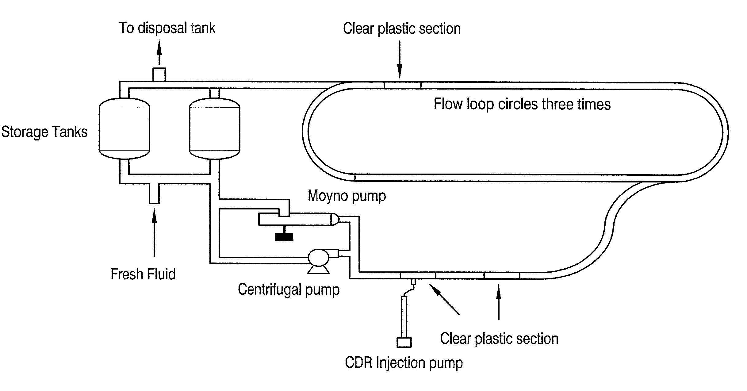
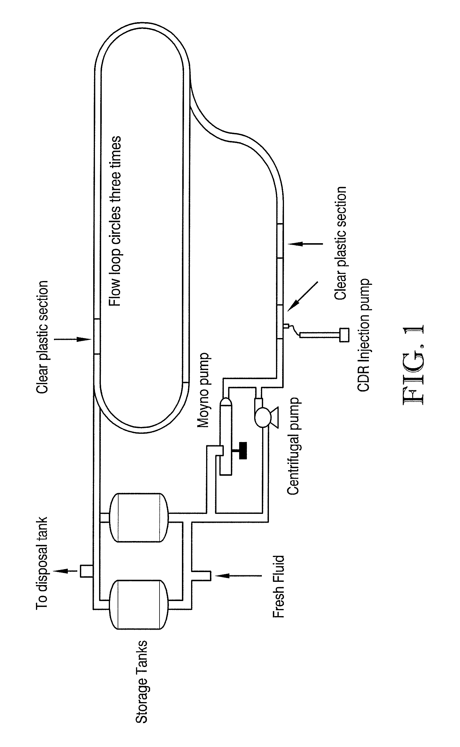
[0061] In this example, the drag reduction capabilities of the 38% poly-2-ethylhexyl methacrylate polymer emulsion prepared in Example 1 were evaluated in a #2 diesel fuel system. The test device used in this example was a two inch Engineering Loop Re-circulation Test apparatus as shown in FIG. 1. This test allowed for the evaluation of drag reducer performance when injected in non-predissolved form into a hydrocarbon fluid in the flow loop. The test was used to simulate performance profiles and drag reducer behavior in field pipelines over a three-hour time period in terms of dissolution, peak performance, and degradation of the drag-reducing polymer.

[0062] In the two inch pipe-loop recirculation test, 600 gallons of diesel at 70° F. was recirculated from a mixed reservoir through a 2-inch diameter pipe loop and back to the reservoir. Approximate holdup in the pipe is 100 gallons. The diesel was recirculated at 42.3 gpm using a low-shear progressing cavity pump. Pressure drop was ...

example 3

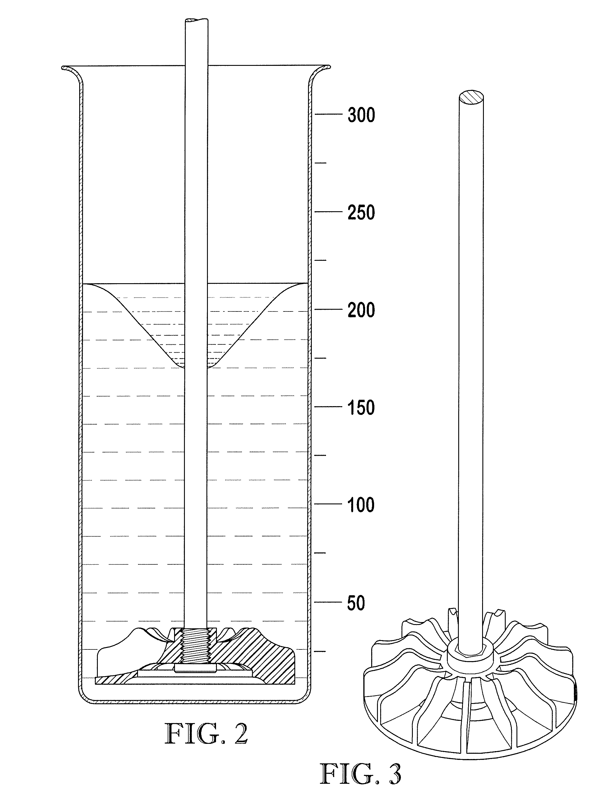
[0073] Toluene (104.15 g) was added to a 600 ml beaker and the beaker placed under an overhead stirrer equipped with a 2 inch diameter 3-blade propeller. The stirrer was adjusted to 250 rpm and 41.675 grams of sorbitan sesquioleate (available as Lumisorb SSO from Lambent Technologies, Skokie, Ill.) was added and mixed for 10 minutes until it dissolved. A Portion of the emulsion prepared in Example 1 (104.175 g) was then added and the systems mixed for 20 minutes. The composition had a density of 0.939 g / ml and a Brookfield LVDVII+ viscosity of 3700 mPa·s using a #4 spindle at 12 rpm. The composition in terms of percent by weight was as follows:

Emulsion from Example 141.67%Toluene41.66%Sorbitan sesquioleate16.67%

[0074] The dissolution rate of this material was measured using the dissolution rate test described above. The results show that the modified emulsion polymer had good dissolution properties which improve with increasing temperature.

Temperature, ° C.Dissolution Rate Const...


PUM

PropertyMeasurementUnit
mean particle sizeaaaaaaaaaa
freezing pointaaaaaaaaaa

Abstract

A modified latex drag reducer and methods of making and using the drag reducer in order to reduce friction losses resulting from turbulent fluid flow through a conduit. Particularly, the modified latex drag reducer is formed from an initial latex which is a product of an emulsion polymerization reaction. The initial latex is then modified, preferably by admixing with at least one low HLB surfactant or at least one solvent, or both, to form a modified latex with an enhanced dissolution rate in a hydrocarbon stream over the initial latex.

Description

RELATED APPLICATIONS [0001] This application is a continuation of U.S. patent application Ser. No. 11 / 026,758, filed Dec. 30, 2004, incorporated by reference herein.BACKGROUND OF THE INVENTION [0002] 1. Field of the Invention [0003] The present invention generally relates to latex drag reducers comprising high molecular weight polymers produced according to an emulsion polymerization reaction and methods of using the same. [0004] 2. Description of the Prior Art [0005] A drag reducer is a composition capable of substantially reducing friction loss associated with the turbulent flow of a fluid through a conduit. Where fluids are transported over long distances, such as in oil and other hydrocarbon liquid pipelines, these friction losses result in inefficiencies that increase equipment and operations costs. Ultra-high molecular weight polymers are known to function well as drag reducers, particularly in hydrocarbon liquids. In general, drag reduction depends in part upon the molecular ...

Claims


Application Information

Patent Timeline
Patent Type & Authority Applications(United States)
IPC IPC(8): F17D1/18C08L23/00C08L31/00C08L39/00C08L47/00
CPCF17D1/17C09K2208/28Y10T137/0391C09K3/00
Inventor HARRIS, WILLIAM F.SMITH, KENNETH W.MILLIGAN, STUART N.JOHNSTON, RAY L.ANDERSON, VINCENT S.
Owner LIQUIDPOWER SPECIALTY PROD INC
Why Eureka
Try Eureka