Heat pipe

a heat pipe and heat pipe technology, applied in the field of heat pipes, can solve the problems of reducing the speed of the condensed liquid in the return to the evaporating section, limiting the maximum heat transfer capacity (qmax) of the heat pipe, and heat pipe often suffers dry-out problems, so as to increase the heat absorbing area enhance the maximum heat transfer capacity of the heat pipe, and reduce heat resistance

Inactive Publication Date: 2007-10-18
HON HAI PRECISION IND CO LTD
View PDF13 Cites 9 Cited by
  • Summary
  • Abstract
  • Description
  • Claims
  • Application Information

AI Technical Summary

Benefits of technology

[0008]The present invention relates to a heat pipe. A heat pipe includes a hollow metal casing. The casing has an evaporating section and a condensing section at respective opposite ends thereof, and an adiabatic section located between the evaporating section and the condensing section. A capillary wick structure is arranged at an inner surface of the hollow metal casing. A sealed heat reservoir is mounted on the evaporating section of the heat pipe to increase heat absorbing area of the heat pipe. The heat pipe is so configured to simultaneously reduce heat resistance and enhance maximum heat transfer capacity of the heat pipe.

Problems solved by technology

However, during the phase change of the working media, the resultant vapor and the condensed liquid flows along two opposite directions, which reduces the speed of the condensed liquid in returning back to the evaporating section and therefore limits the maximum heat transfer capacity (Qmax) of the heat pipe.
As a result, the heat pipe often suffers dry-out problem at the evaporating section as the condensed liquid cannot be timely sent back to the evaporating section of the heat pipe.
Furthermore, the heat pipe has a high ratio of length to radius so that the heat is dissipated during transmission of the vapor and a part of the vapor prematurely changes into condensed liquid before reaching the condensing section.
However, by this method, the maximum heat transfer capacity of the heat pipe is reduced accordingly.

Method used


Image

  • Heat pipe
  • Heat pipe
  • Heat pipe

Examples


Embodiment Construction

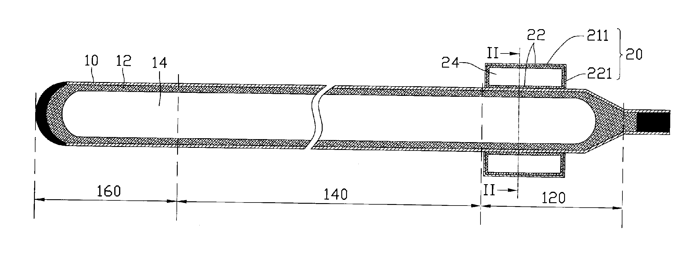
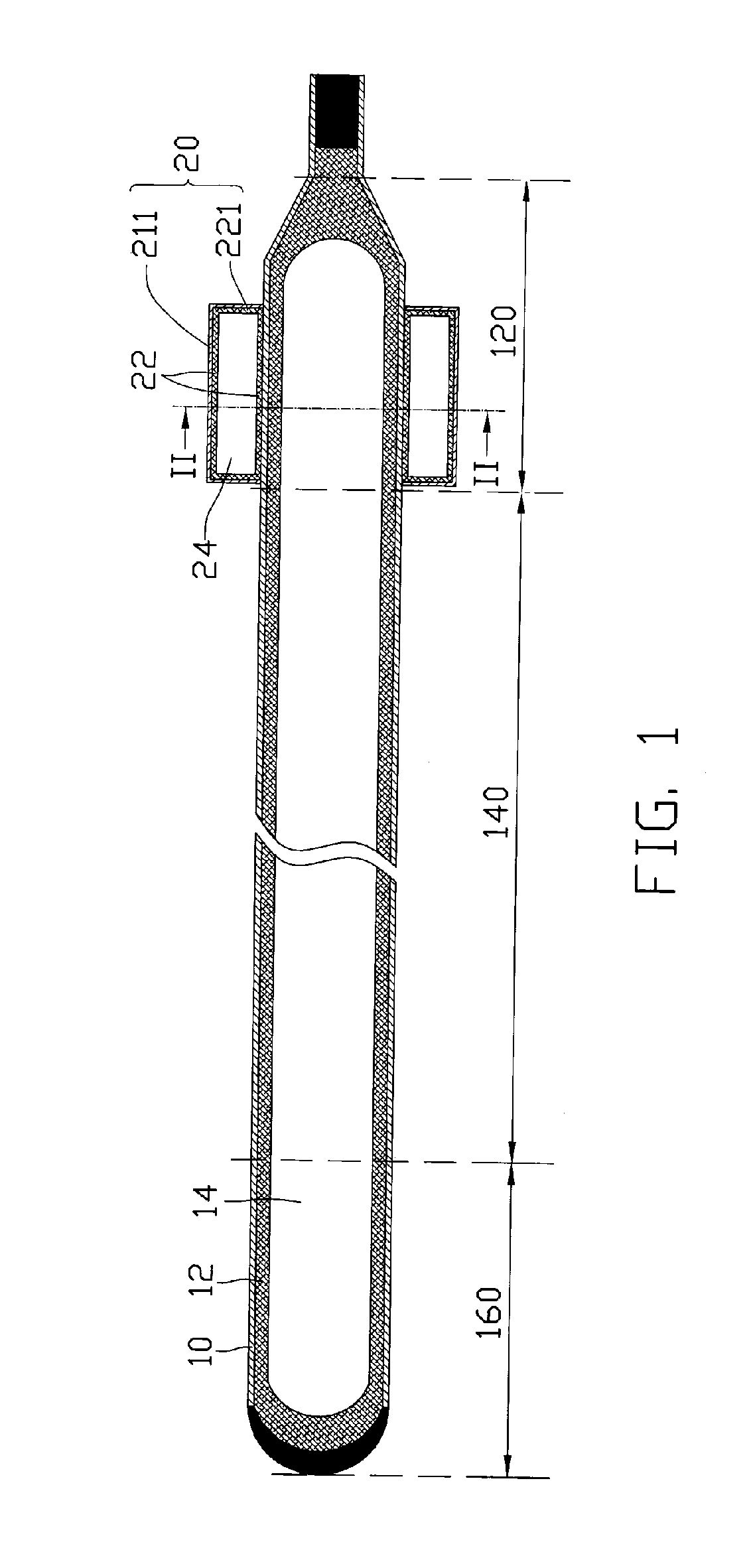
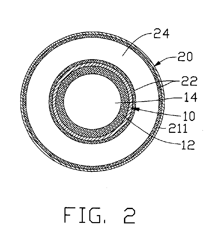
[0017]FIGS. 1 and 2 show a heat pipe in accordance with one embodiment of the present invention. The heat pipe has a cylindrical configuration and includes a metal casing 10 made of highly thermally conductive materials such as copper or copper alloys, a first working fluid (not shown) contained in the casing 10 and a first capillary wick structure 12 arranged in an inner surface of the casing 10. The casing 10 includes an evaporating section 120 at one end, a condensing section 160 at the other end and an adiabatic section 140 arranged between the evaporating section 120 and the condensing section 160. A sealed heat reservoir 20 is mounted on the evaporating section 120. A vapor channel 14 is defined along an axial direction of the heat pipe and is located at a center of the casing 10. The vapor channel 14 is surrounded by an inner surface of the first capillary wick structure 12 so as to guide vapor to flow therein.

[0018]The heat reservoir 20 has a hollow cylindrical configuration...


PUM


Abstract

A heat pipe includes a hollow metal casing (10). The casing has an evaporating section (120) and a condensing section (160) at respective opposite ends thereof, and an adiabatic section (140) located between the evaporating section and the condensing section. A capillary wick structure (12) is arranged at an inner surface of the hollow metal casing. A sealed heat reservoir (20) is mounted on the evaporating section of the heat pipe to increase heat absorbing area of the heat pipe. The heat reservoir has working fluid and a capillary wick structure (22) therein. Heat generated by a heat source is first absorbed by the heat reservoir and then transferred to the evaporating section of the metal casing.

Description

FIELD OF THE INVENTION[0001]The present invention relates generally to a heat pipe as heat transfer / dissipating device, and more particularly to a heat pipe which has a heat reservoir for quickly absorbing heat received from an electronic component such as a Central Processing Unit (CPU) to increase the maximum heat transfer capacity and reduce the temperature differential across the length of the heat pipe.DESCRIPTION OF RELATED ART[0002]It is well known that a heat pipe is generally a vacuum-sealed pipe. A porous wick structure is provided on an inner face of the pipe, and where the pipe is filled with at least a phase changeable working media employed to carry heat. Generally, according to positions from which heat is input or output, the heat pipe has three sections, namely, an evaporating section, a condensing section and an adiabatic section between the evaporating section and the condensing section.[0003]In use, the heat pipe transfers heat from one place to another place mai...

Claims


Application Information

Patent Timeline
Patent Type & Authority Applications(United States)
IPC IPC(8): F28D15/00
CPCF28D15/0275
Inventor LIU, TAY-JIANTUNG, CHAO-NIENHOU, CHUEN-SHUWANG, JI-FENGHE, QIAN-HUA
Owner HON HAI PRECISION IND CO LTD
Why Eureka
Try Eureka