High light output lamps having a phosphor embedded glass/ceramic layer

a technology of phosphor and glass, applied in the direction of discharge tube luminescnet screens, electric discharge lamps, electrical equipment, etc., can solve the problems of luminescent material used in these lamps which is subject to break down, devices are subject to outside air pressure, thermal shock, vibration,

Inactive Publication Date: 2007-10-18
AVAGO TECH WIRELESS IP SINGAPORE PTE
View PDF5 Cites 90 Cited by
  • Summary
  • Abstract
  • Description
  • Claims
  • Application Information

AI Technical Summary

Benefits of technology

[0005] A lamp having a glass/ceramic composite having phosphor embedded therein is disclosed for use with high power light sources. In one embodiment, the phosphor is embedded in a

Problems solved by technology

Such devices are subjected to outside air pressure, thermal shocks, as well as vibrations.
Under such conditions, thermal stress causes each component to repeatedly expand and contract thereby compromising their structural integrity.
Compounding the problem is that newly developed light-emitting elements, which can emit light in the near-ultraviolet range with high-luminosity, are now available.
This is especially true for the luminescent material used in these lamps which is subject to break down due to environmental reasons.
While this resin also has high flexibility, its surface is soft and thus its m

Method used


Image

  • High light output lamps having a phosphor embedded glass/ceramic layer
  • High light output lamps having a phosphor embedded glass/ceramic layer
  • High light output lamps having a phosphor embedded glass/ceramic layer

Examples


Embodiment Construction

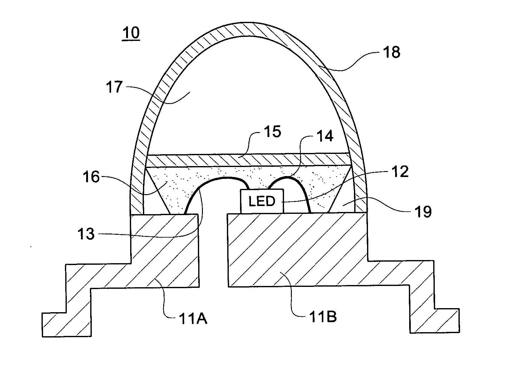
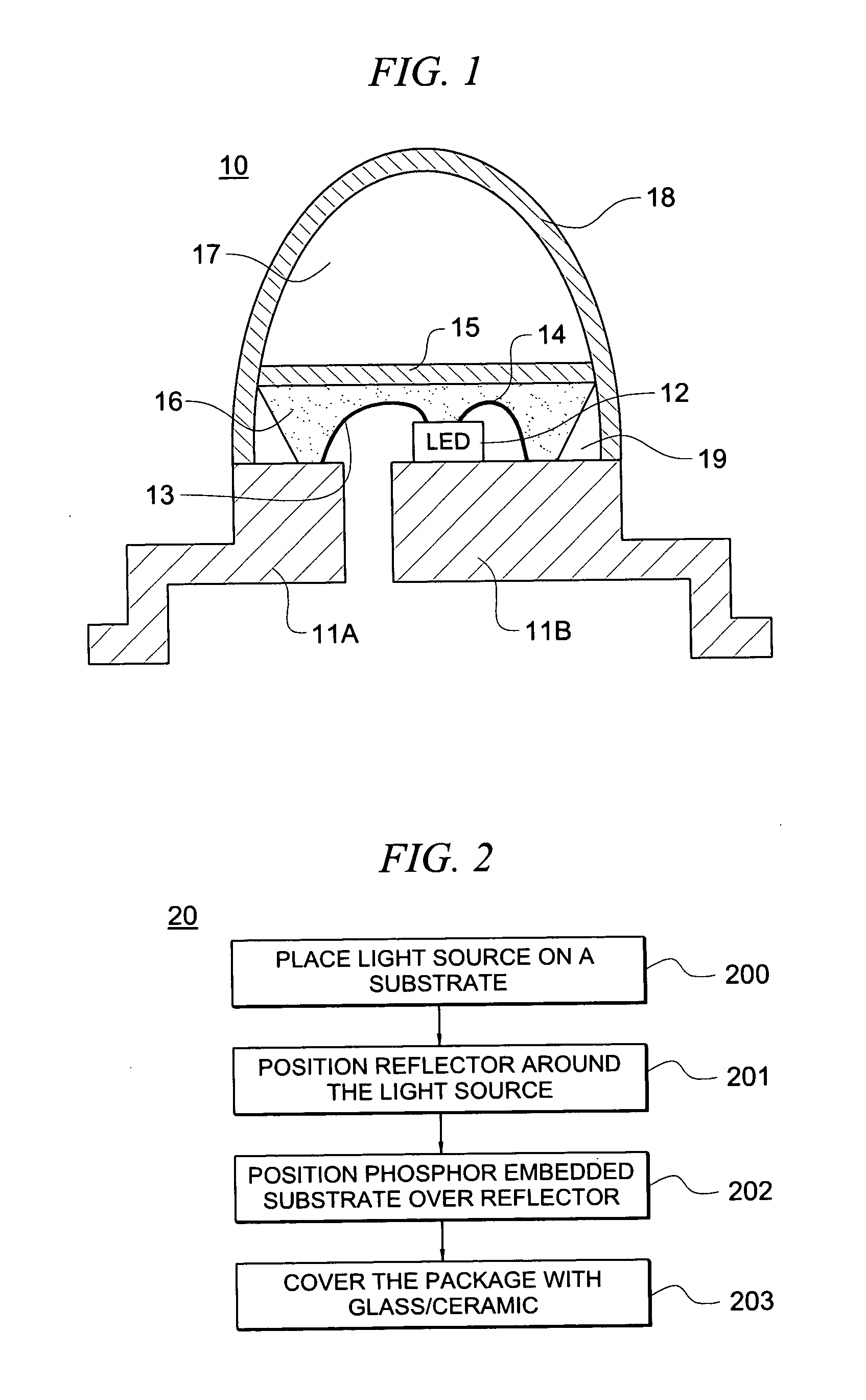
[0009]FIG. 1 shows one embodiment of a lamp in accordance with one invention in which lamp 10 has base structure elements 11A and 11B. The light source, in this embodiment an LED, such as LED 12, is mounted to base element 11B, which element together with element 11A is metallic in order to act as a heat transfer path to move heat away from the light source. Light source 12 is controlled by wires 13 and 14 bonded to the respective base elements. The light source is within (optimal) reflector cup 19 which can, if desired, be made from reflective glass and / or metal.

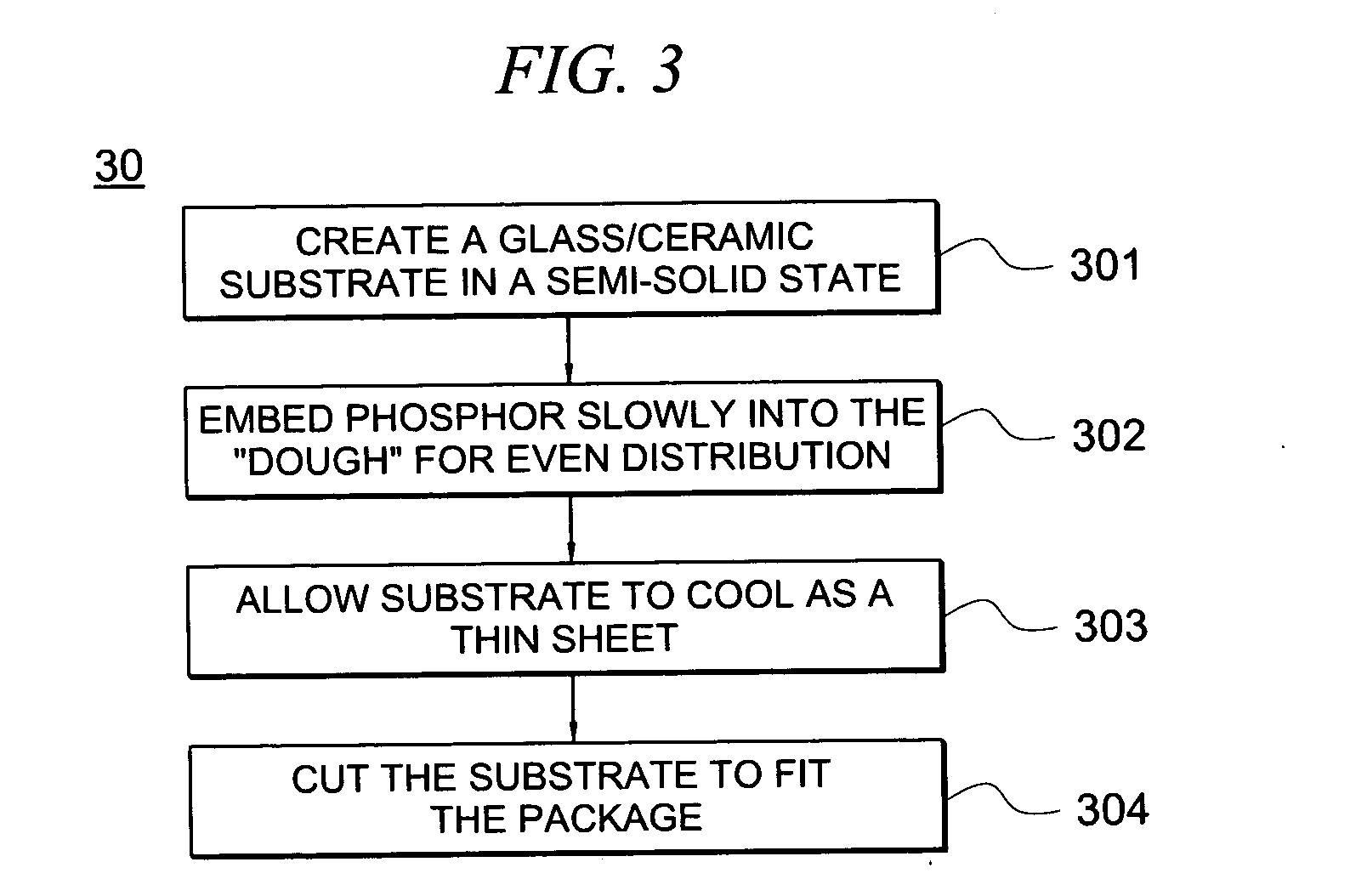
[0010] Optical gel 16 surrounds light source 12, and layer 15 is positioned above the optical gel. Layer 15 is, in the embodiment shown, a glass / ceramic matrix with phosphor embedded therein. In one embodiment the phosphor is constructed as a thin film and is quantum dot phosphor.

[0011] Surrounding layer 15 is, in one embodiment, air gap 17. Shell 18 surrounds the device. In this embodiment, shell 18 is glass and provides...


PUM


Abstract

A lamp having a glass/ceramic composite having phosphor embedded therein is disclosed for use with high power light sources. In one embodiment, the phosphor is embedded in a thin film as quantum dots. In one embodiment, a glass shell surrounds the light source and the composite phosphor matrix to protect the lamp from outside environmental conditions.

Description

TECHNICAL FIELD [0001] This invention relates to high light output lamps and move particularly to such lamps that use wavelength changing materials to generate specific colors. BACKGROUND OF THE INVENTION [0002] As light-emitting devices become more widely used it is inevitable that they will be desired for use under increasingly more severe circumstances and conditions and under increased power and light output. For example, in applications for aircraft or automotive vehicles, the light-emitting devices are used as high as +80° C. or more, or as low as −20° C. or less. Such devices are subjected to outside air pressure, thermal shocks, as well as vibrations. Under such conditions, thermal stress causes each component to repeatedly expand and contract thereby compromising their structural integrity. Compounding the problem is that newly developed light-emitting elements, which can emit light in the near-ultraviolet range with high-luminosity, are now available. It would be desirable...

Claims


Application Information

Patent Timeline
IPC IPC(8): H01J1/62
CPCH01L33/483H01L33/501H01L33/54H01L33/58H01L2224/48247H01L2224/48091H01L2924/00014H01L2224/48257H01L2924/181H01L2924/00012
Inventor YIN, CHUA BEE
Owner AVAGO TECH WIRELESS IP SINGAPORE PTE
Why Eureka
Try Eureka