Photomultiplier

a multi-channel photomultiplier and photomultiplier technology, applied in the field of photomultipliers, can solve the problems of no improvement, achieve the effects of improving the high-speed response properties of the multi-channel photomultiplier as a whole, reducing electron transit time differences, and improving the electron transit time differences in each electron multiplier channel

Inactive Publication Date: 2007-10-18
HAMAMATSU PHOTONICS KK
View PDF19 Cites 12 Cited by
  • Summary
  • Abstract
  • Description
  • Claims
  • Application Information

AI Technical Summary

Benefits of technology

[0008]The inventors have studied conventional multichannel photomultipliers in detail, and as a result, have found problems as follows. Namely, in each of the conventional multichannel photomultipliers, because electron multiplications are performed by electron multiplier channels that are assigned in advance according to photoelectron emission positions of the photocathode, the positions of the respective electrodes are designed optimally to reduce electron transit time differences according to each electron multiplier channel. By such improvement of the electron transit time differences in each electron multiplier channel, improvements are made in the electron transit time differences of the multichannel photomultiplier as a whole and consequently, the high-speed response properties of the multichannel photomultiplier as a whole are improved.
[0010]In order to overcome the above-mentioned problems, it is an object of the present invention to provide a photomultiplier that is significantly improved as a whole in such response time characteristics as TTS (Transit Time Spread) and CTTD (Cathode Transit Time Difference) by realizing a configuration for reducing emission-position-dependent photoelectron transit time differences of photoelectrons emitted from a photocathode.
[0011]Presently, developments of PET devices added with a function of TOF (Time-of-Flight) are performed. In photomultipliers used in such a PET device with TOF, CRT (Coincident Resolving Time) response characteristic also becomes important The conventional photomultipliers do not satisfy the request to CRT response characteristic in such a PET with FOP. Therefore, Thus, in the present invention, to make an improvement using an existing PET device as a base, the orbit-designing is performed to enable CRT measurement satisfying the request for PET device with FOP while keeping a bulb outer diameter the same as the present diameter. Specifically, the TTS, which is correlated to the CRT response characteristic, is improved and the orbit-designing is performed so that both the TTS within an entire faceplate and the TTS within each light incidence region are improved.
[0016]In particular, in the photomultiplier according to the present invention, the mesh electrode is arranged in an inclined state with respect to the tube axis. By this structure, an electric field near the photocathode is made uniform and increased in electric field strength. By the electric field strength being increased, the electron transit time differences among the photoelectrons emitted from the photocathode are shortened and such response time characteristics as the TTS, CTTD, etc., are improved significantly.

Problems solved by technology

The inventors have studied conventional multichannel photomultipliers in detail, and as a result, have found problems as follows.
However, in such multichannel photomultipliers, no improvements had been made in regard to the spread of the average electron transit time differences among the electron multiplier channels and further improvement of the high-speed response properties is required.

Method used


Image

  • Photomultiplier
  • Photomultiplier
  • Photomultiplier

Examples


Embodiment Construction

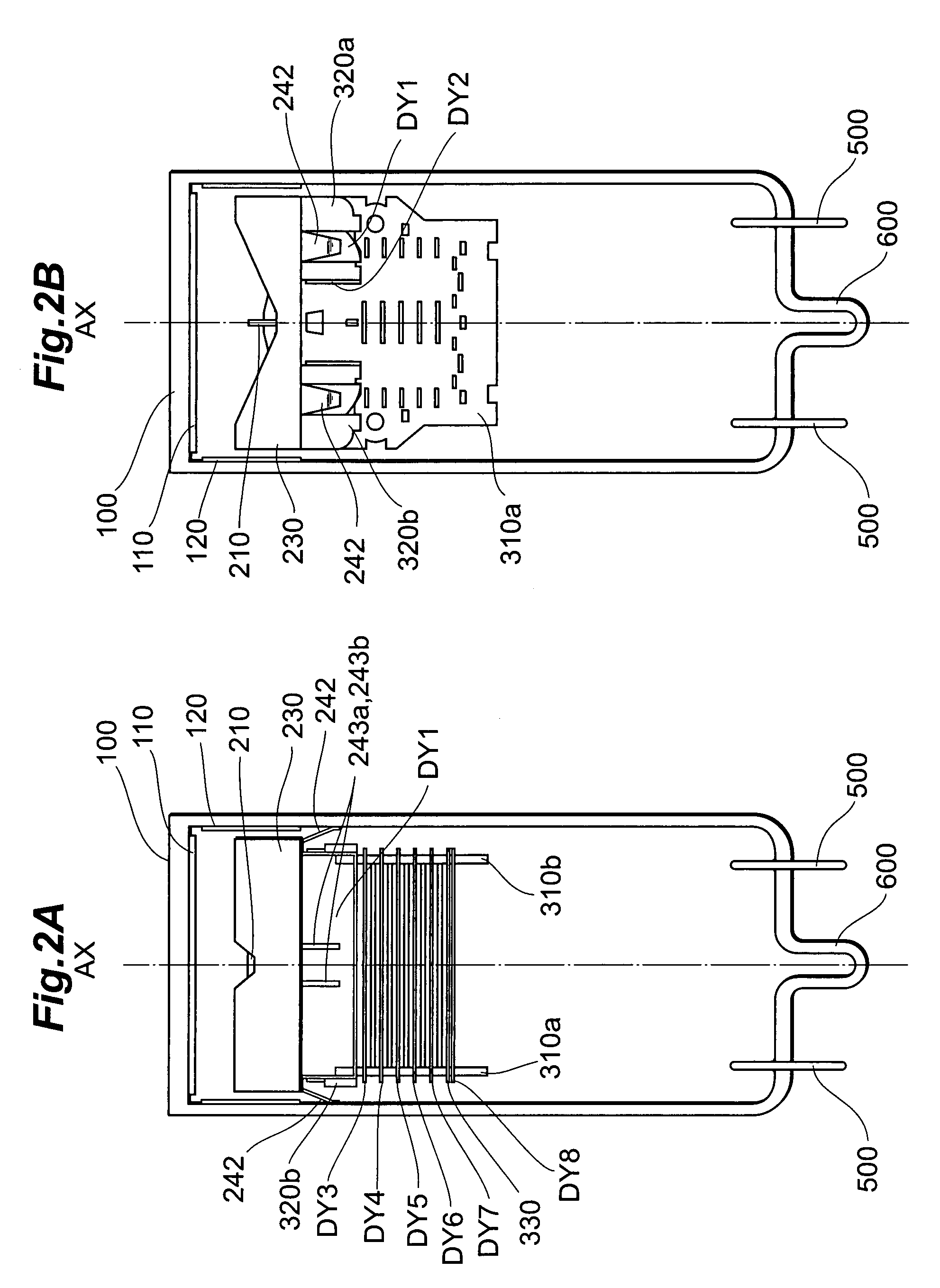
[0034]In the following, embodiments of a photomultiplier according to the present invention will be explained in detail with reference to FIGS. 1, 2A, 2B, 3, 4A-5C, 6-10, and 11A-13C. In the explanation of the drawings, constituents identical to each other will be referred to with numerals identical to each other without repeating their overlapping descriptions.

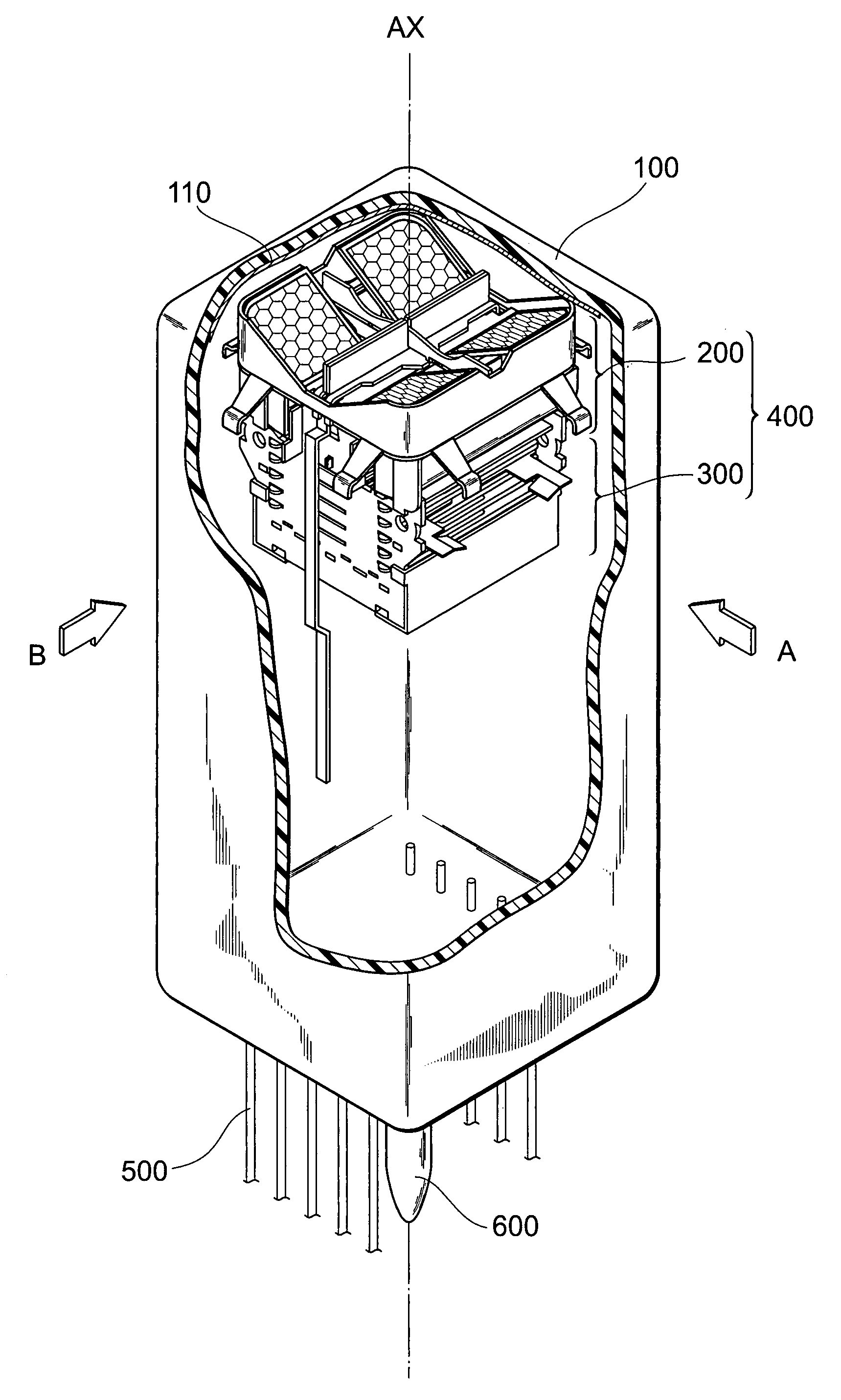
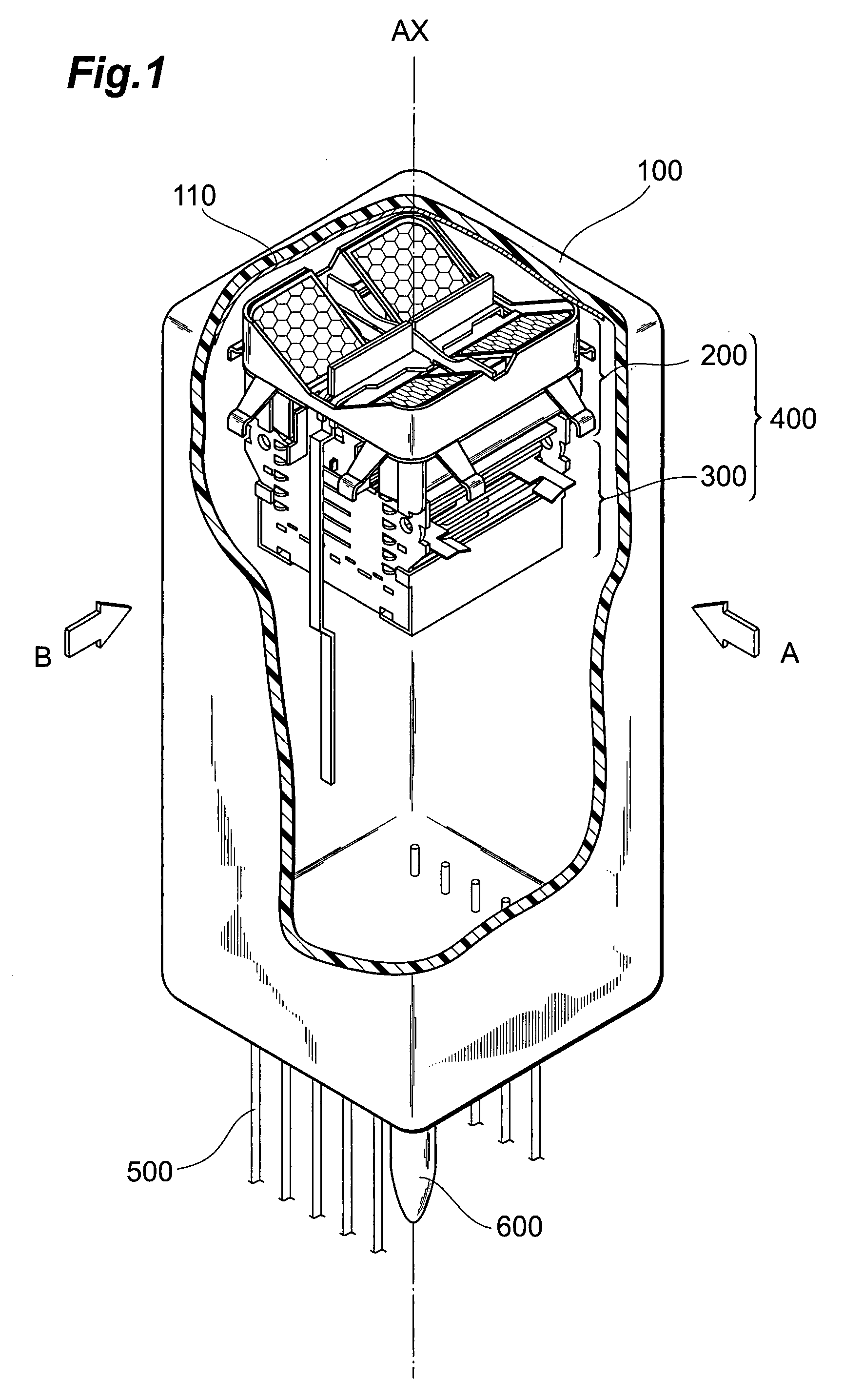
[0035]FIG. 1 is a partially cutaway view showing a schematic configuration of an embodiment of a photomultiplier according to the present invention.

[0036]As shown in FIG. 1, the photomultiplier according to the present invention comprises a sealed container 100, with a pipe 600, which is used to depressurize the interior to a predetermined degree of vacuum (and the interior of which is filled after vacuum drawing), provided at a bottom portion, and comprises a photocathode 110 and an electron multiplier section 400 which are provided inside the sealed container 100.

[0037]The sealed container 100 is constituted by a cylindrica...


PUM


Abstract

The present invention relates to a photomultiplier having a configuration for improving response time characteristics. The photomultiplier comprises at least a sealed container, a photocathode, and an electron multiplier section. The electron multiplier section has an upper unit and a lower unit. The upper unit includes a focusing electrode, a mesh electrode, and a first dynode, among a multiple stages of dynodes, being a dynode at which the photoelectrons from the photocathode arrive. The lower unit includes the subsequent dynodes while excluding the first dynode from the multiple stages of dynodes, and a pair of insulating supporting members that clampingly hold the subsequent dynodes. The mesh electrode is positioned in an inclined state with respect to a tube axis.

Description

CROSS-REFERENCE TO RELATED APPLICATION[0001]This application claims priority to Provisional Application Ser. No. 60 / 781,891 filed on Apr. 14, 2006 by the same Applicant, which is hereby incorporated by reference in its entirety.BACKGROUND OF THE INVENTION[0002]1. Field of the Invention[0003]The present invention relates to a photomultiplier, in response to incidence of photoelectrons, capable of cascade-multiplying secondary electrons by successive emission of the secondary electrons in multiple stages.[0004]2. Related Background Art[0005]Development of TOF-PET (Time-of-Flight PET) as a next-generation PET (Positron Emission Tomography) device is being pursued actively in the field of nuclear medicine in recent years. Particularly, in a TOF-PET device, because two gamma rays, emitted from a radioactive isotope administered into a body, are measured simultaneously, a large number of photomultipliers of excellent, high-speed response properties are used as measuring devices that are d...

Claims


Application Information

Patent Timeline
Patent Type & Authority Applications(United States)
IPC IPC(8): H01J43/20H01J43/04
CPCH01J43/18
Inventor OHMURA, TAKAYUKIKIMURA, SUENORI
Owner HAMAMATSU PHOTONICS KK
Why Eureka
Try Eureka