
Systems, methods and devices for dual closed loop modulation controller for nonlinear RF amplifier

Active Publication Date: 2007-10-18
VIASAT INC
View PDF6 Cites 9 Cited by
  • Summary
  • Abstract
  • Description
  • Claims
  • Application Information

AI Technical Summary

Benefits of technology

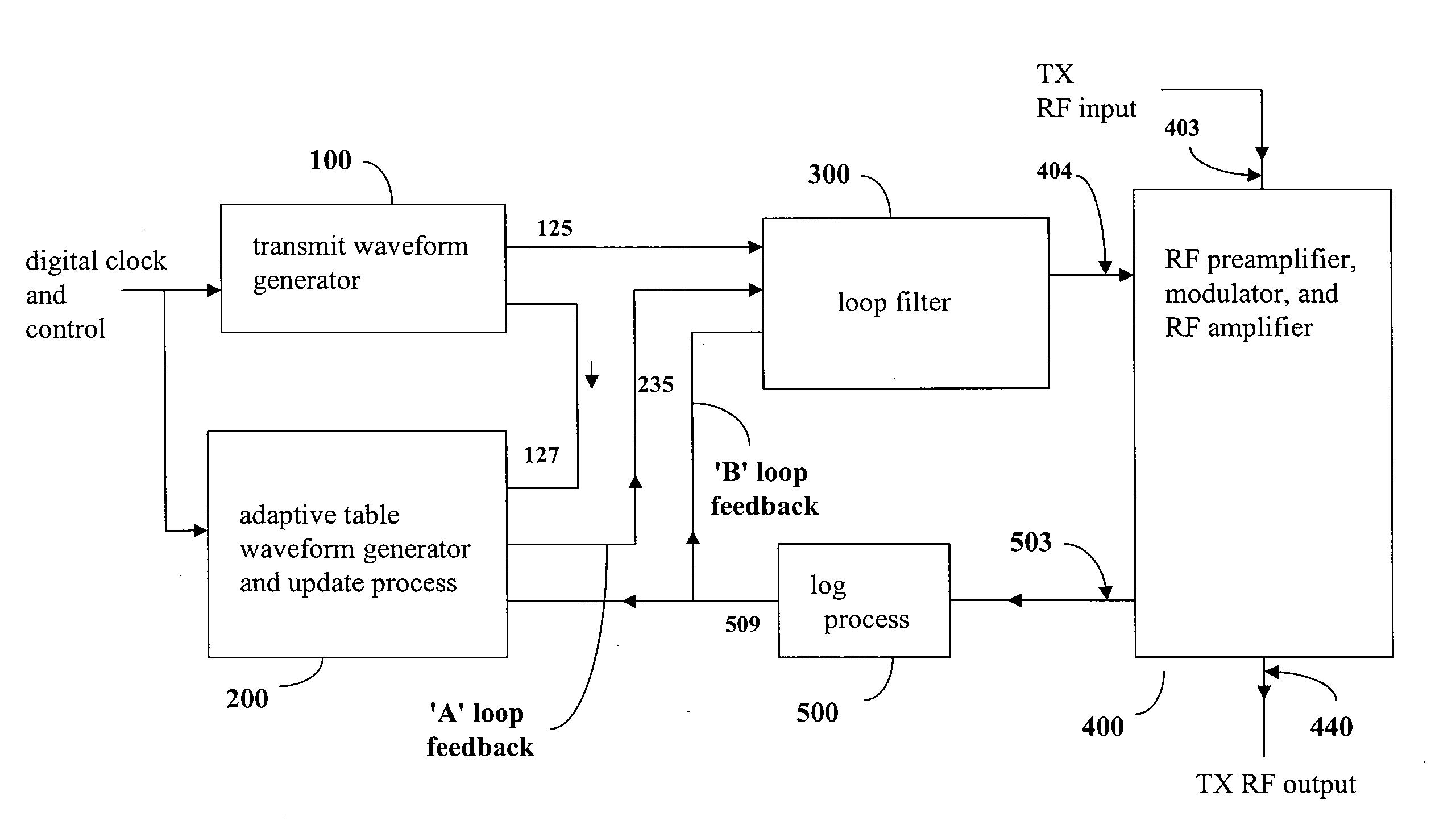
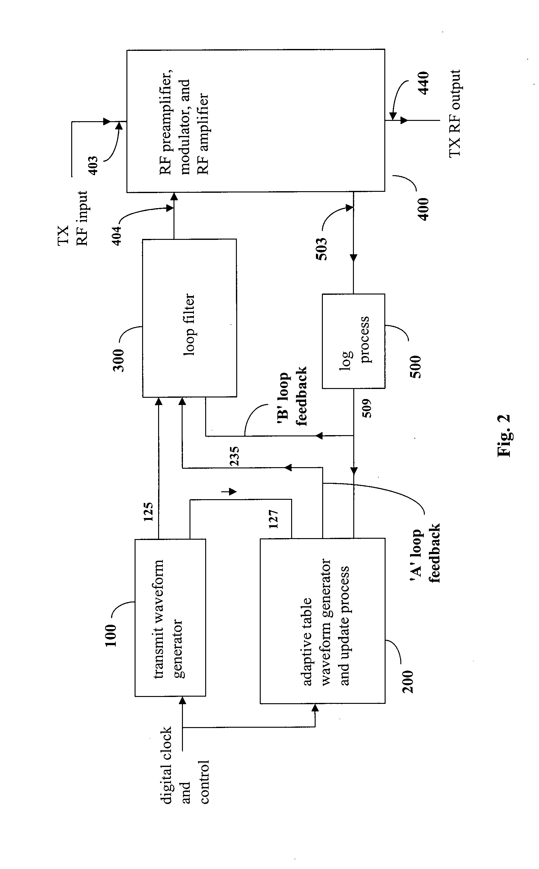
[0011] In another exemplary embodiment, a RF envelope amplitude control method comprises the steps of: receiving a reference waveform signal at an RF envelope amplitude controller; receiving a feedback signal, based on the RF output of an RF transmit amplifier, at the RF envelope amplitude controller; comparing the feedback signal to the reference waveform signal; adjusting an adaptive table to store a waveform value at a memory location in the adaptive table; combining the reference waveform signal, the first feedback signal and the second feedback signal to form an amplifier control signal that facilitates adjusting the amplifier RF output signal to achieve a close approximation of a desired waveform envelope.

Problems solved by technology

Unfortunately, RF transmitters and their components are often subject to relatively severe temperature stresses, which can make it more difficult to match the desired waveform envelope.
However, during the interval between transmitted pulses, no RF energy is allowed to be transmitted; therefore a closed loop condition cannot exist during this interval.
A single control loop, operating under this constraint, having sufficient gain and bandwidth to meet the accuracy requirements over some portions of the output envelope, will likely be unstable over other portions of the output envelope.
The instability is due primarily to the nonlinearities in the controlled element (the actual RF amplifier chain) and the absence of a valid closed loop condition in the time interval between RF pulses.
However, the waveform rise and fall times for GSM are approximately 30 μsec versus 3.5 μsec for Joint Tactical Radio System (“JTRS”) and TACAN and 0.25 μsec for TDMA, therefore the previous solutions do not provide the required control bandwidth.
By contrast, due to the low gain of the devices required for JTRS-compatible applications, many stages are needed to achieve the required gain and output power.
By contrast, the maximum allowed spurious, or modulation dependent, RF sideband output levels of a JTRS / TACAN transmitter are relatively low, and can be seriously degraded (increased) by excessive gain in the waveform control loop.

Method used


Image

  • Systems, methods and devices for dual closed loop modulation controller for nonlinear RF amplifier
  • Systems, methods and devices for dual closed loop modulation controller for nonlinear RF amplifier
  • Systems, methods and devices for dual closed loop modulation controller for nonlinear RF amplifier

Examples


Embodiment Construction

[0020] While the exemplary embodiments herein are described in sufficient detail to enable those skilled in the art to practice the invention, it should be understood that other embodiments may be realized and that logical and mechanical changes may be made without departing from the spirit and scope of the invention. Thus, the following detailed description is presented for purposes of illustration only and not of limitation.

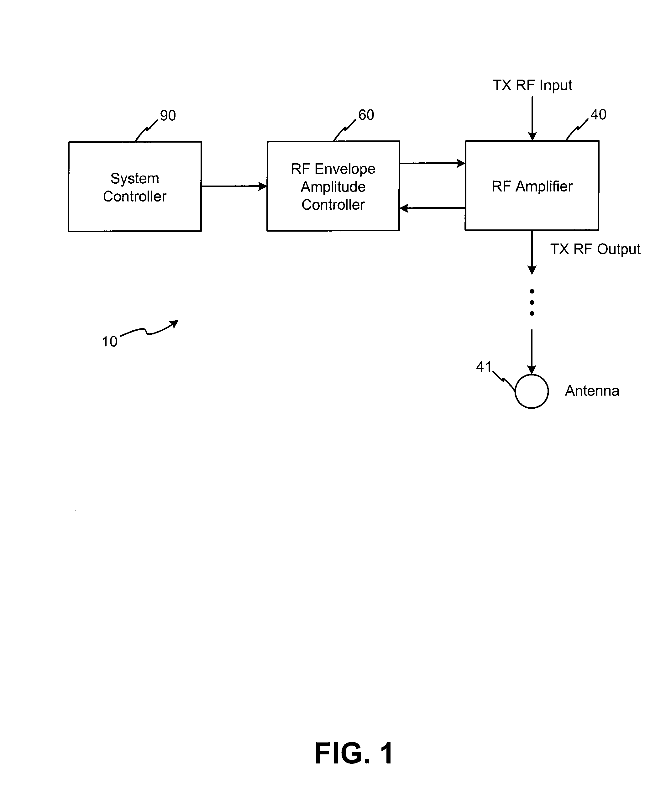
[0021] In accordance with various exemplary embodiments of the invention, systems, methods and devices are configured for providing RF envelope amplitude control. The control system is configured to facilitate amplification, in non-linear RF amplifiers, of RF signals prior to transmission. Moreover, the control system is configured to facilitate amplification of RF signals having stringent requirements on the waveform output envelopes.

[0022] In accordance with an exemplary embodiment of the present invention, a transmitter system is configured to receive an t...


PUM


Abstract

In accordance with various exemplary embodiments of the present invention, systems, methods and devices are configured to facilitate RF envelope amplitude control. For example, a RF envelope amplitude control system comprises: a RF amplifier, wherein the RF amplifier is associated with a feedback device that is configured to create a first feedback signal representing the power in an RF output signal; a transmit waveform generator configured to generate a reference waveform signal; an adaptive table waveform generator configured to compare the reference waveform signal and the first feedback signal and to create a second feedback signal based on that comparison; and a loop filter configured to combine the reference waveform signal, the first feedback signal, and the second feedback signal to form an amplifier control signal, wherein the amplifier control signal is provided to the RF amplifier to adjust the RF output signal to conform to a specified RF envelope.

Description

FIELD OF INVENTION [0001] The present invention generally relates to RF amplifiers, and more particularly, to envelope controllers for nonlinear RF amplifiers. BACKGROUND OF THE INVENTION [0002] In some types of radio frequency (“RF”) transmitters, the RF output signal of an RF amplifier is required to closely match one of several predetermined amplitude envelopes. For example, RF transmitters exist where the transmitter output consists of continuous wave (“CW”) or phase modulated RF pulses that are required to closely match one of several predetermined amplitude envelopes. One such transmit mode is known as Tactical Air Command And Navigation (“TACAN”) involving amplitude modulation. Another is Time Domain Multiple Access (“TDMA”) involving phase modulation. Unfortunately, RF transmitters and their components are often subject to relatively severe temperature stresses, which can make it more difficult to match the desired waveform envelope. [0003] In addition, transmitter frequency...

Claims


Application Information

Patent Timeline
IPC IPC(8): H04B1/04H01Q11/12
CPCH03C1/62H04L27/08H04B1/04H03F3/189
Inventor LANG, DAVID R.
Owner VIASAT INC
Learn More