
Eureka
For R&D, Eureka makes reading and utilizing patents & technical documents easy.
Eureka AIR
Designed for self-driven R&D workflows. Generate viable solutions, solve complex R&D challenges, empower your innovation with AI.

Eureka Materials
Designed for material experts only. Revolutionize your material R&D, from search, analyze, to developing new materials.

TechResearch
Generate reliable direction feasibility study reports for your R&D in just a few steps.

TechSeek
Discover and master advanced knowledge NOW. Basics, ideas, possibilities, all at once.

TechMind
As an expert in R&D Theories, TechMind can generates customized viable solutions instantly.

TechRisk
Analyze your overall solution with one click, know your potential R&D risks in advance.

TechMonitor
Get weekly tech updates, stay abreast of the latest tech innovations and key insights.
Image processing system, information processor, and method of processing information that can notify that job is completed
- Summary
- Abstract
- Description
- Claims
- Application Information
AI Technical Summary
Benefits of technology
Problems solved by technology
Method used
Image

Examples
first embodiment
[0031]1) System Components
[0032]Initially an image processing system corresponding to a first embodiment of the present invention will be described in configuration.
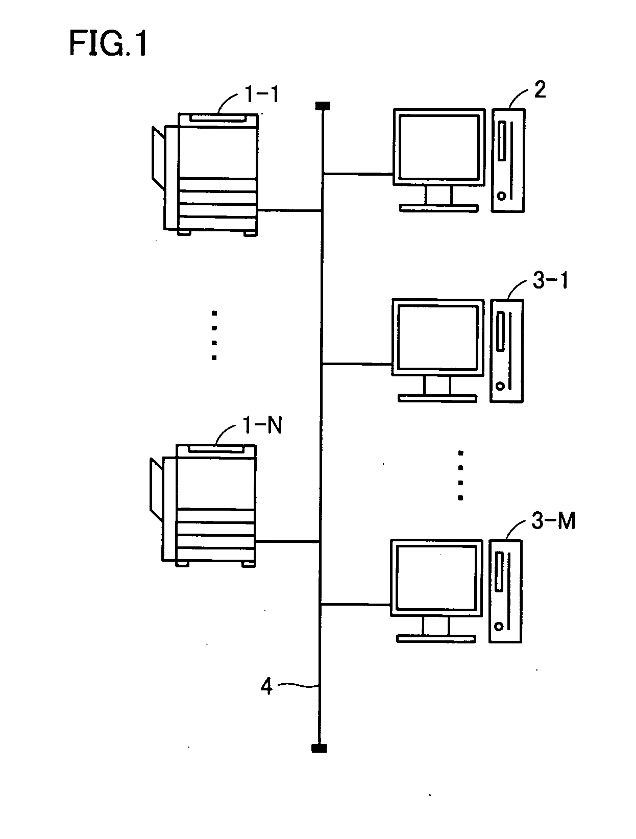
[0033]With reference to FIG. 1, an image processing system includes N image processors 1-1 to 1-N, a server 2, and M information processors 3-1 to 3-M, wherein N and M are each any integer. All these processors are connected on a network 4.
[0034]Network 4 may be a network utilizing a dedicated line such as a local area network (LAN), a network utilizing a public network, or a wireless network.
[0035]Image processors 1-X forms, on a sheet, an original image read out on its own, or a duplicate of an image generated from data to be printed transmitted from an information processor 3-Y, wherein X=1 to N and Y=1 to M.
[0036]Data to be printed may be a plotting instruction in page description language, i.e. a plotting instruction issued by the operating system or application program of information processor 3-Y converted into a ...
second embodiment
[0083]With reference to FIG. 7 a process performed in an image processing system of a second embodiment of the present invention by CPU 301 of information processor 3-Y will specifically be described. Note that the process shown in FIG. 7 corresponds to an exemplary variation of that shown in FIG. 6. The image processing system of the present embodiment is similar in configuration to that of the first embodiment unless otherwise specified.
[0084]With reference to FIG. 7, in this exemplary variation, CPU 301 performs steps SA10-SA70, which are similar to those indicated in the flow chart shown FIG. 6 and corresponding thereto. Then if at step SA70 CPU 301 determines that the time counted by timer 305 has reached a defined value, CPU 301 proceeds to step SA71 to determine whether there is a user present in front of its own processor. If so, then CPU 301 proceeds to step SA80, otherwise returns to step SA10 without effecting a process performed in step SA80 et seq. for notification to u...
third embodiment
[0088]With reference to FIG. 8 a process performed in an image processing system of a third embodiment of the present invention by CPU 301 of information processor 3-Y will specifically be described. Note that the process shown in FIG. 8 corresponds to an exemplary variation of that shown in FIG. 6. The image processing system of the present embodiment is similar in configuration to that of the first embodiment unless otherwise specified.
[0089]With reference to FIG. 8, CPU 301 initially proceeds to step SB10 to clear timer 309.
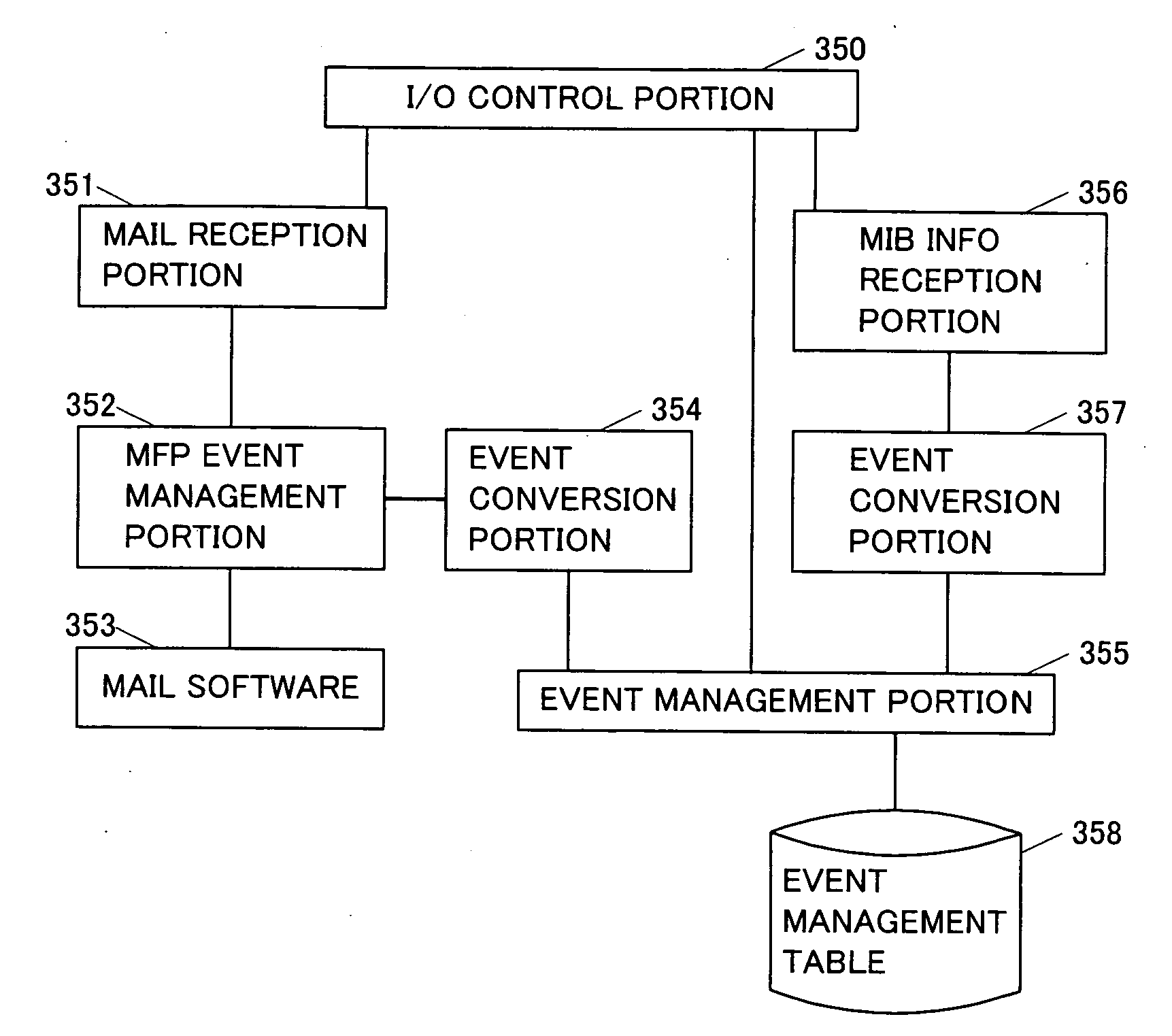
[0090]Then CPU 301 proceeds to step SB20 to determine whether notification that an event has arisen has been received from any of image processors 1-1 to 1-N and if so CPU 301 proceeds to step SB30 to store the content(s) of the notification to the event management table and proceeds to step SB40. Note that steps SB20 and SB30 are assumed to indicate a process identical to steps SA20-SA50 shown in FIG. 6. If CPU 301 determines that such notification is not rec...
PUM
 Abstract
Description
Claims
Application Information
 - R&D Engineer
- R&D Manager
- IP Professional
- Industry Leading Data Capabilities
- Powerful AI technology
- Patent DNA Extraction
Browse by: Latest US Patents, China's latest patents, Technical Efficacy Thesaurus, Application Domain, Technology Topic, Popular Technical Reports.
© 2024 PatSnap. All rights reserved.Legal|Privacy policy|Modern Slavery Act Transparency Statement|Sitemap|About US| Contact US: help@patsnap.com