Device for generating hydrogen for use in internal combustion engines

a technology for internal combustion engines and hydrogen, which is applied in the field of fuel in internal combustion engines, can solve the problems of increasing fuel cost, affecting the economy of most drivers, and requiring a large amount of environmental cost, so as to reduce the amount of fuel an internal combustion engine consumes, increase the efficiency of the internal combustion engine, and reduce the effect of hydrocarbons

Inactive Publication Date: 2007-10-25
SMOLA MATTHEW M +1
View PDF1 Cites 44 Cited by
  • Summary
  • Abstract
  • Description
  • Claims
  • Application Information

AI Technical Summary

Benefits of technology

[0017] In accordance with the present invention, there is provided mobile elecrolyzer that is both functional and effective in reducing the amount of fuel an internal combustion engine consumes and there by cuts down the hydrocarbons that the internal combustion engine produces. A plastic housing with separate chambers holds the electrolyte. The chambers are vented separately with the hydrogen being introduced into the air intake of the engine. Adding hydrogen to a hydrocarbon fuel has been proven to increase the efficiency of an internal combustion engine. The present invention provides a low cost device that can create hydrogen when it is needed. The present invention provides a system that can generate hydrogen on board for a vehicle or a internal combustion engine.

Problems solved by technology

The rising cost of fossil fuels has had a negative impact on the economy of most drivers.
The cost of fuel is expected to rise and the environmental cost must be figured in too.
Moreover, the refill time for hydrogen is substantially longer than that for gasoline when the hydrogen is to be stored on-board.
We note that the authors state that this system would not be practical to generate hydrogen as the sole fuel for an engine.
This system requires carefully controlled catalytic action and temperature range and has limitations for startup and transient response.

Method used


Image

  • Device for generating hydrogen for use in internal combustion engines
  • Device for generating hydrogen for use in internal combustion engines

Examples


Embodiment Construction

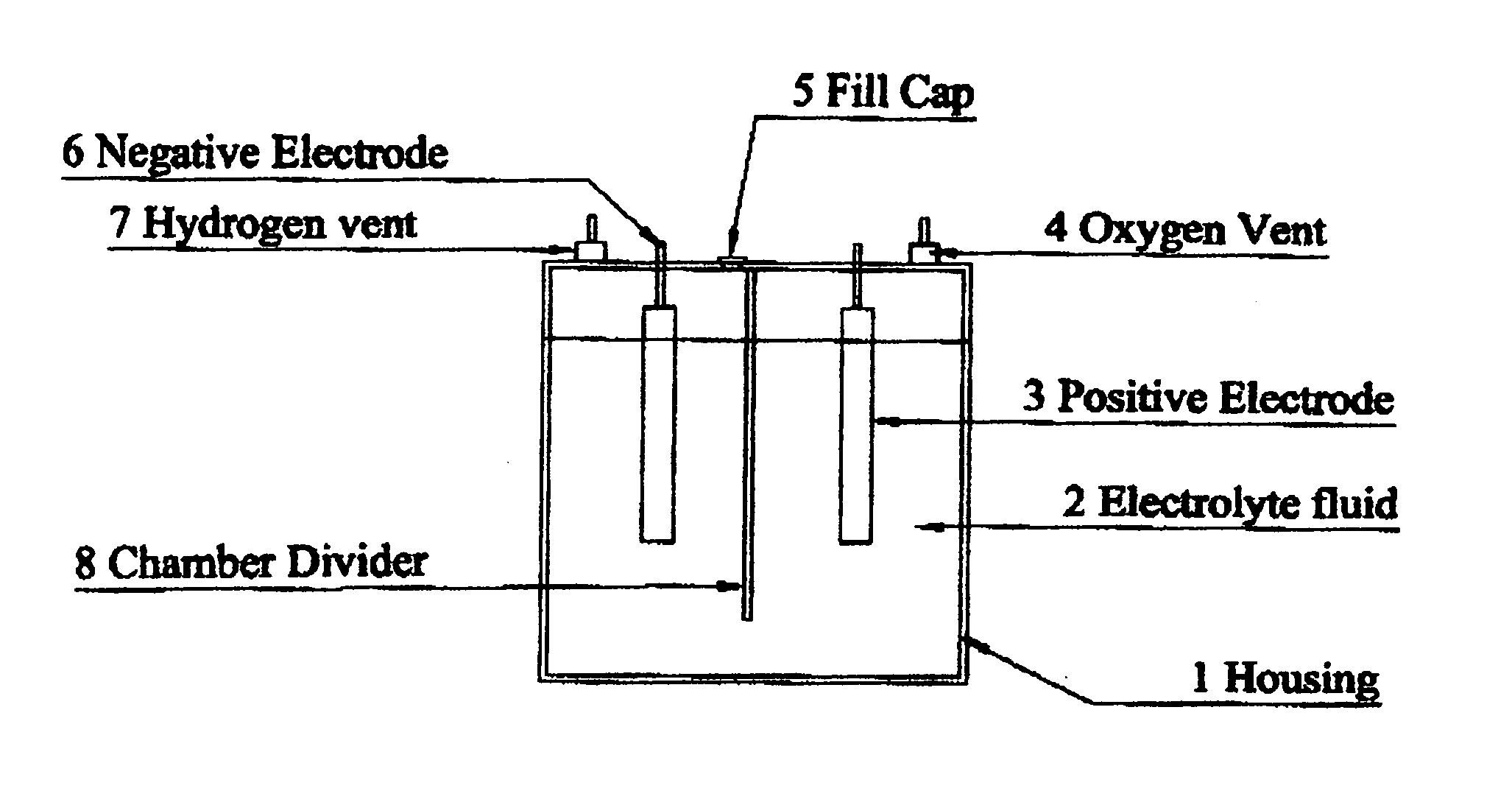
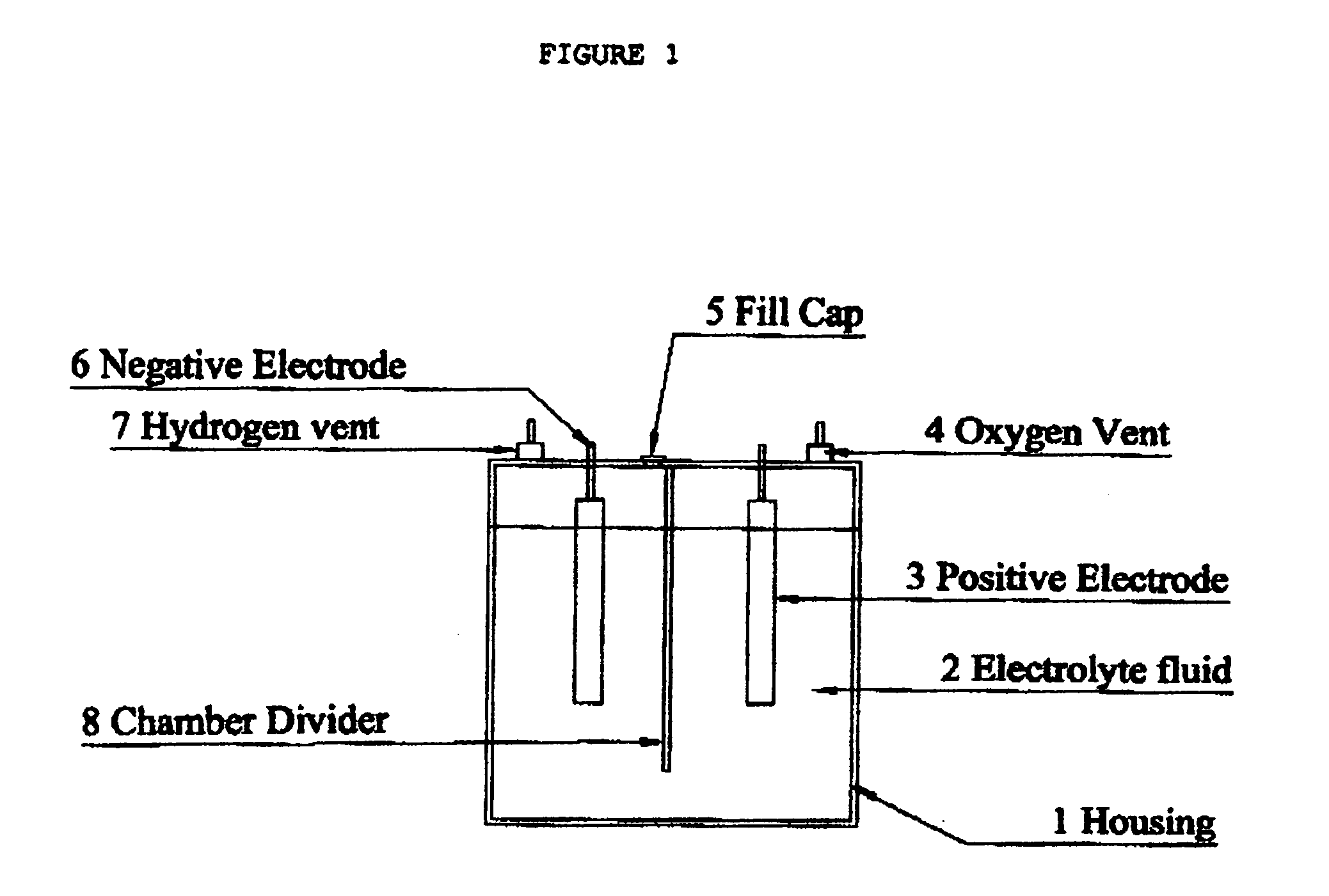
[0023]FIG. 1 which is a front view of the housing 1 for the electrodes provides a space to add water and space for the electrode to come in contact with water. The Electrolyte fluid 2 increases the conductivity of the fluid. The Positive Electrode 3 provides a device to bring the positive current in contact with the electrolyte fluid 2. The Oxygen vent (4) provides an exit for the oxygen gas hat is created. The fill cap (5) provides a place to fill the device with the fluid. The Negative Electrode 6 provides a place for the negative current to come in contact with the fluid. The Hydrogen vent 7 provides a exit for the hydrogen gas that is created The Chamber Divider 8 (6) separated the hydrogen from the oxygen.

[0024] Since other modifications and changes varied to fit particular operating requirements and environments will be apparent to those skilled in the art, the invention is not considered limited to the example chosen for purposes of disclosure, and covers all changes and mod...


PUM

PropertyMeasurementUnit
currentaaaaaaaaaa
volumesaaaaaaaaaa
weightsaaaaaaaaaa

Abstract

An electrolysis conversion system for converting water into hydrogen and oxygen, includes a housing in which are housed electrodes. The electrodes are immersed in an electrolyte and are connected to a positive and negative sides of an energy source. The housing is a non conductive material that has chambers to separate the hydrogen and the oxygen The present invention further discloses a method of utilizing the electrolyzer in conjunction with the fuel system of an internal combustion engine to improve the efficiency of said internal combustion engine.

Description

RELATED APPLICATIONS [0001] The present application is related to U.S. Pat. No. 6,536,551, issued Mar. 25, 2003, included by reference herein. [0002] The present application is related to U.S. Pat. No. 5,244,558, issued Sep. 24, 1992, by Chiang, included by reference herein. [0003] The present application is related to U.S. Pat. No. 6,096,178, issued Aug. 24, 1998, by Amirav Tzanani, included by reference herein. [0004] The present application is related to U.S. Pat. No. 6,689,259, issued Oct. 18, 2002, by Klene, included by reference herein. FIELD OF THE INVENTION [0005] The present invention relates to fuel in internal combustion engines and, more particularly, to use in autos and trucks to increase the fuel economy. The present invention generally relates to systems including converters for supplying hydrogen-rich gas to internal combustion engines. The invention more particularly relates to onboard generation systems for use in vehicles and the like in which the systems are capa...

Claims


Application Information

Patent Timeline
Patent Type & Authority Applications(United States)
IPC IPC(8): C25B9/00
CPCC25B1/02C25B9/00F02B43/10Y02T10/32F02M25/12Y02T10/121F02B2043/106Y02T10/12Y02T10/30
Inventor SMOLA, MATTHEW M.SCHUBERT, FRANK
Owner SMOLA MATTHEW M
Why Eureka
Try Eureka