Pressure Vessel

a pressure vessel and pressure technology, applied in the direction of electrochemical generators, transportation and packaging, container discharging methods, etc., can solve the problems of deteriorating the comfort of the cabin, wasting space in the car-mounted state, and inability to make effective use of free space existing in motor vehicles, so as to improve the pressure resistance and save weight. , the effect of reducing the thickness

Inactive Publication Date: 2007-10-25
HONDA MOTOR CO LTD +1
View PDF17 Cites 31 Cited by
  • Summary
  • Abstract
  • Description
  • Claims
  • Application Information

AI Technical Summary

Benefits of technology

[0052] In the pressure vessel according to par. 13), the reinforcing wall is stationarily formed in the dome-shaped communicating member. The dome-shaped communicating member thus improves in pressure resistance, and can be made relatively smaller in thickness for the sake of weight saving of the pressure vessel.
[0053] In the pressure vessels according to par. 14) to 16), the open ends of the liners of at least two adjoining vessel structures are connected to each other by the connecting part, and at least one reinforcing wall of the communicating member is connected to the connecting part. Thus, even when a large force acts in the longitudinal direction, the fixed part of the dome-shaped communicating memb

Problems solved by technology

Since motor vehicles have limitations in vehicle width, and thus also have limitations in increasing the length of the trunk, the higher capacity of the pressure vessel must be achieved by increasing the diameter of the trunk.
When the diameter of the trunk is increased, however, it is impossible to make effective use of free space

Method used


Image

  • Pressure Vessel
  • Pressure Vessel
  • Pressure Vessel

Examples


embodiment 1

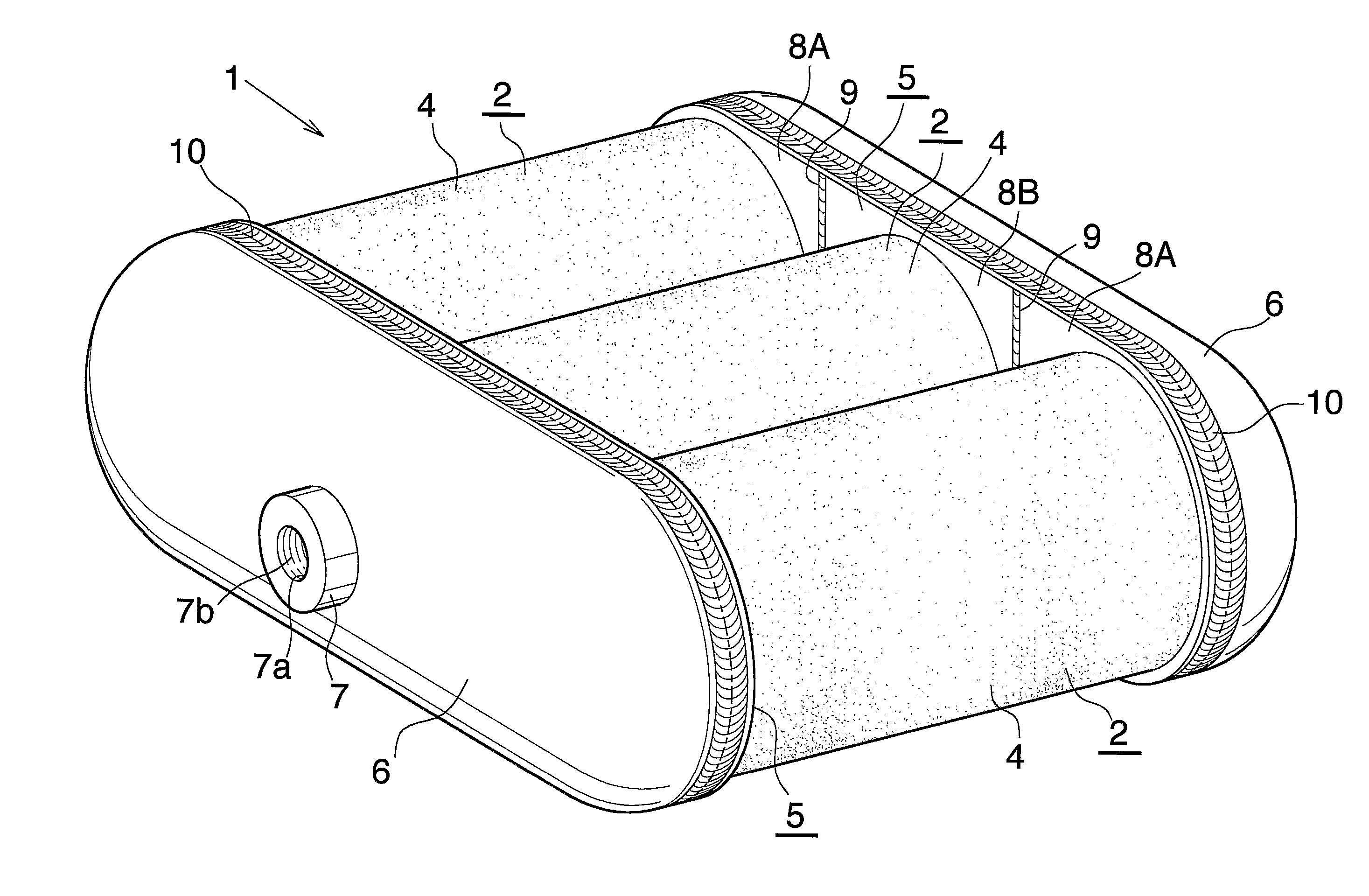
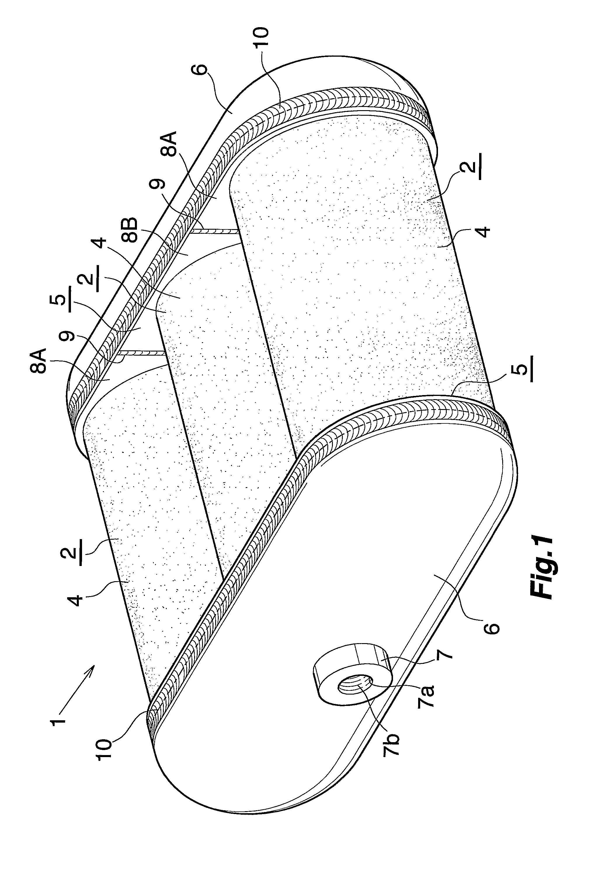
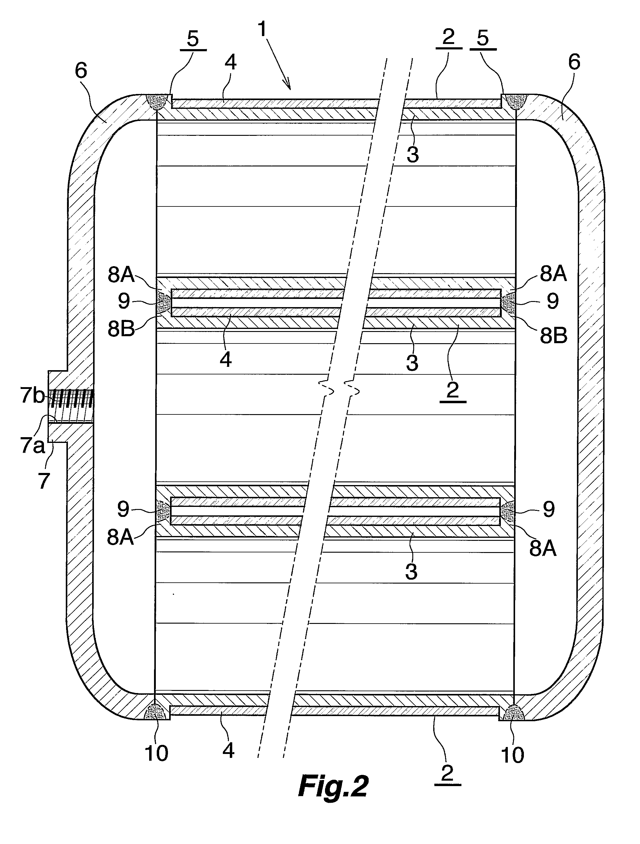
[0076] This embodiment is shown in FIGS. 1 to 7. FIGS. 1 to 3 show a pressure vessel. FIGS. 4 to 6 show the method of fabricating the pressure vessel. In addition, FIG. 7 shows an example of measures for the case when a higher pressure resistance is required.

[0077] In FIGS. 1 to 3, the pressure vessel (1) comprises: a plurality of vessel structures (2) each composed of a cylindrical liner (3) made of aluminum, having openings at both ends and lying with its axis in a lateral direction, and a fiber reinforced resin layer (4) covering an outer periphery of a peripheral wall of the liner (3), the vessel structures (2) being arranged in parallel in a front-to-back direction with the axes of the liners (3) on an identical horizontal plane; end plates (5) made of aluminum, formed stationarily across both right and left ends of the liners (3) of all the vessel structures (2); and outward-bulging dome-shaped communicating members (6) made of aluminum, fixed to the respective end plates (5)...

embodiment 2

[0093] This embodiment is shown in FIG. 10.

[0094] With the pressure vessel of this embodiment, the end plates (5) are each made of a single metal plate, or aluminum plate (30) here, having through holes (31) for the open ends of the liners (3) to be fitted into. Then, both ends of the individual liners (3) are fitted into the through holes (31) in the respective aluminum plates (30). The areas of the aluminum plates (30) around the through holes (31) and the open ends of the liner (3) are joined from outside in the axial direction of the liners (3) by an appropriate method such as the friction agitation joining method. Incidentally, no fiber reinforced resin layer (4) is formed on both ends of the liners (3) where to be fitted into the through holes (31) in the aluminum plates (30). The method for joining the aluminum plates (30) and the liners (3) is not limited to the friction agitation joining method.

[0095] The aluminum plates (30) are made of, for example, any one of JIS A2000...

embodiment 3

[0097] This embodiment is shown in FIG. 11.

[0098] The pressure vessel of this embodiment does not use the end plates (5). Both ends of the liners (3) of adjoining vessel structures (2) are connected and integrated with each other by the intervention of plate-like connecting members (35) made of metal, or made of aluminum here. More specifically, semicircular notches (36) for halves of the ends of two adjoining liners (3) to be fitted to are formed in both sides of the connecting members (35) Then, the halves of both ends of the liners (3) are fitted into the notches (36) in the connecting members (35). The areas of the connecting members (35) around the notches (36) and both ends of the liner (3) are joined from outside in the axial direction of the liners (3) by an appropriate method such as the friction agitation joining method. Incidentally, no fiber reinforced resin layer (4) is formed on both ends of the liners (3) where to be fitted into the notches (36) in the connecting mem...


PUM

PropertyMeasurementUnit
Diameteraaaaaaaaaa
Lengthaaaaaaaaaa
Areaaaaaaaaaaa

Abstract

A pressure vessel arranging and integrating a plurality of vessel structures each including a cylindrical liner opened at both ends and a fiber reinforced resin layer covering the outer periphery of the peripheral wall of the liner. Dome-shaped communicating members bulging outward are fixed across both respective ends of the liners of the vessel structures, thereby making the interiors of these liners communicate with each other and closing the open ends of these liners. This pressure vessel can be installed with no wasted space, and also allows an increase in capacity.

Description

CROSS REFERENCE TO RELATED APPLICATIONS [0001] This application is an application filed under 35 U.S.C. §111(a) claiming the benefit pursuant to 35 U.S.C. §119(e) (1) of the filing dates of Provisional Applications Nos. 60 / 586,720, 60 / 598,051, and 60 / 598,052 filed Jul. 12, 2004, Aug. 3, 2004, and Aug. 3, 2004, respectively, pursuant to 35 U.S.C. §111(b).TECHNICAL FIELD [0002] The present invention relates to pressure vessels for use as pressure vessels for storing hydrogen gas or natural gas serving as a fuel for power generation, or for storing oxygen gas, for example, in the automobile industry, housing industry, military industry, aerospace industry, medical industry, etc. [0003] The term “aluminum” as used herein and in the appended claims includes aluminum alloys in addition to pure aluminum. BACKGROUND ART [0004] In order to control air pollution, efforts have been made in recent years for developing natural gas motor vehicles and fuel cell motor vehicles which produce clean e...

Claims


Application Information

Patent Timeline
IPC IPC(8): B65D6/02
CPCF17C1/00Y02E60/50F17C1/16F17C13/084F17C2201/0104F17C2201/0109F17C2201/0147F17C2201/0166F17C2201/0171F17C2201/035F17C2201/054F17C2201/056F17C2203/012F17C2203/0604F17C2203/0617F17C2203/0619F17C2203/0621F17C2203/0646F17C2203/0648F17C2203/0658F17C2203/066F17C2203/0663F17C2203/0665F17C2203/0668F17C2203/067F17C2203/0673F17C2205/0111F17C2205/013F17C2205/0142F17C2205/0305F17C2209/2136F17C2209/2154F17C2209/221F17C2209/222F17C2209/227F17C2209/232F17C2209/234F17C2221/011F17C2221/012F17C2221/033F17C2223/0123F17C2223/035F17C2223/036F17C2260/011F17C2260/012F17C2260/018F17C2270/0168F17C2270/0178F17C2270/0184F17C2270/0186F17C2270/02F17C2270/05F17C2270/07H01M8/04208H01M2250/20Y02E60/321Y02T90/32F17C1/14Y02E60/32Y02T90/40
Inventor SHIMADA, TOSHIAKIKAWAMATA, YASUJI
Owner HONDA MOTOR CO LTD
Why Eureka
Try Eureka