System and method for multilaterating a position of a target using mobile remote receiving units

a multi-latering and target technology, applied in direction finders, directions using radio waves, instruments, etc., can solve problems such as errors in each ru, degrade the overall position accuracy of the system, and affect the accuracy of multi-lateration systems

Active Publication Date: 2007-10-25
SAAB INC
View PDF6 Cites 88 Cited by
  • Summary
  • Abstract
  • Description
  • Claims
  • Application Information

AI Technical Summary

Benefits of technology

[0012] It is an object of the present invention to provide a system and method for determining the position of a target by multilateration, without requiring the use of stationary, pre-surveyed RUs.
[0015] In another embodiment of the present invention, at least one receiving unit includes a GPS receiver and one or more sensors (e.g., speedometer, magnetic compass, accelerometer, gyroscope, altimeter). The sensors detect the physical conditions of the receiving unit (e.g., its motion and trajectory relative to the previous position determined by the GPS receiver or other means). Another aspect of this embodiment is the receiving unit includes a Kalman filter that uses positions determined by the GPS receiver (or other means) and motion data supplied by the sensors to determine a smoothed receiving unit position. Yet another aspect of this embodiment is that the position derived from the GPS receiver (or other means) and motion data can be fed back to the GPS receiver and other GPS receivers co-located with the receiving unit to aid the GPS receivers with time synchronization.

Problems solved by technology

As with any detection and location system, there are errors associated with a multilateration system.
For example, each RU will have errors based on RU inherent properties such as clock drift and system processing latency.
One notable limitation for using the known multilateration techniques is that each RU 10 and the reference transponder 12 are required to be physically located at carefully surveyed locations.
Relocating or moving an operating RU is unlikely and in any event must be done offline since the uncertainty incurred due to movement of the RU greatly degrades the overall position accuracy of the system.
The immobility of the RUs limits such multilateration systems to applications where the RUs are stationary.
In emergency or disaster situations, the stationary RUs that are located at surveyed locations are frequently inoperable due to damage and / or lack of power.
For example, government officials are often unable to re-open an airport for several days after a disaster (e.g., a hurricane), because the local surveillance systems are not functioning.
The inability to provide sufficient surveillance to re-open an airport in turn creates a bottleneck slowing the flow of relief aid into the affected area.
Another notable limitation on using known multilateration techniques is the need for a reference transponder 12 that is located where the reference transponder has a clear view of each RU to time synchronize or calibrate the multilateration system.

Method used


Image

  • System and method for multilaterating a position of a target using mobile remote receiving units
  • System and method for multilaterating a position of a target using mobile remote receiving units
  • System and method for multilaterating a position of a target using mobile remote receiving units

Examples


Embodiment Construction

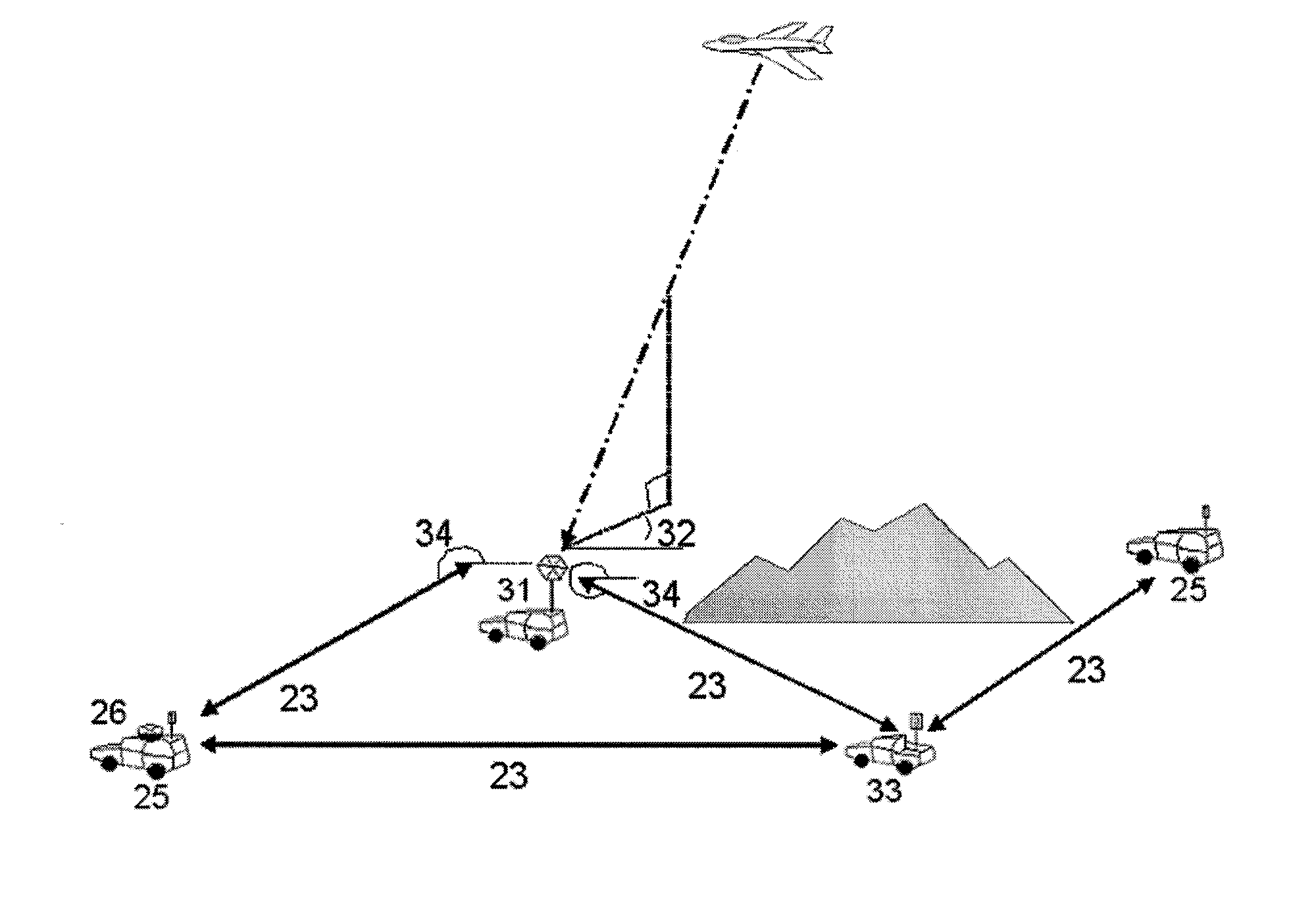
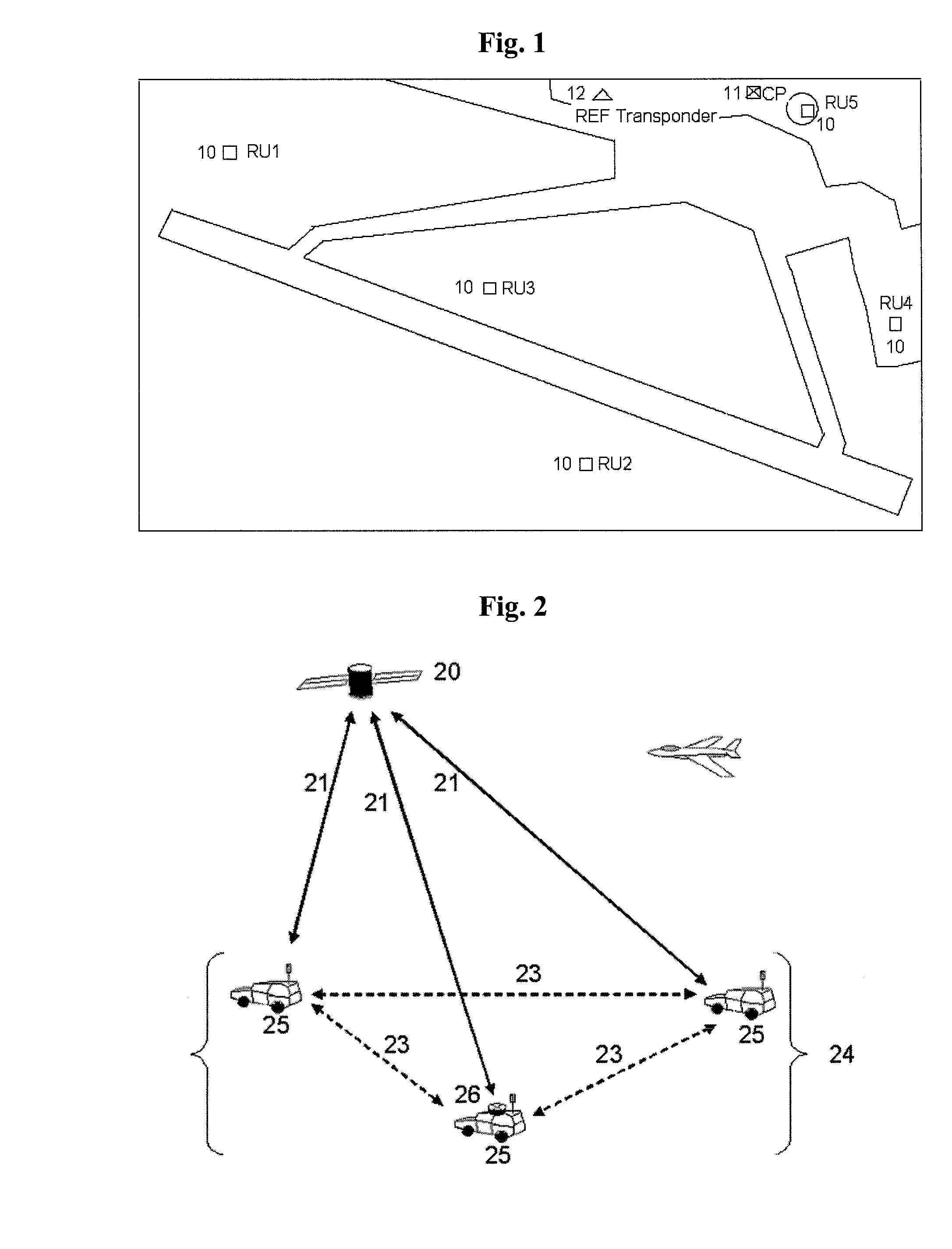
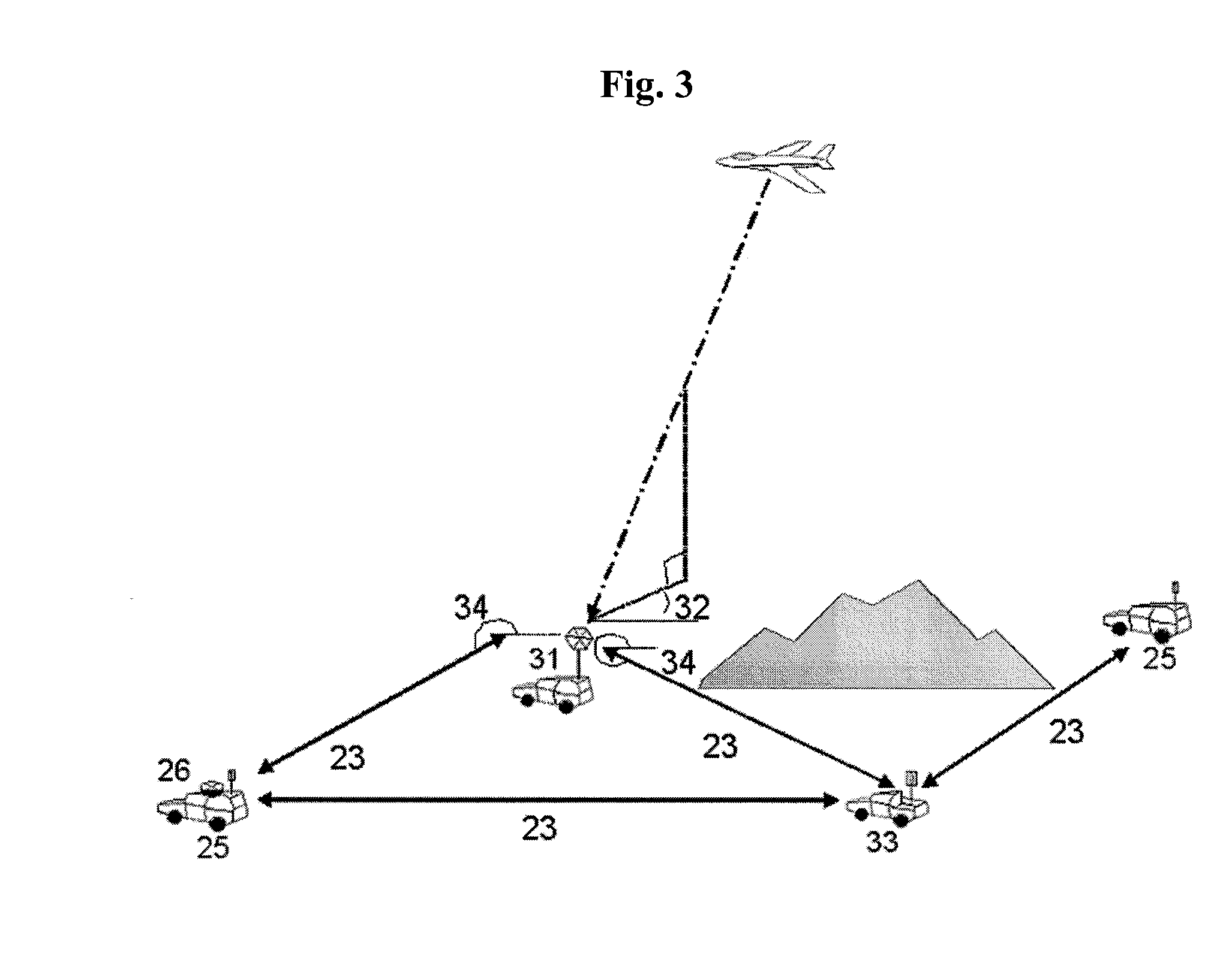
[0036] The system and method of the present invention determine target location by signal processing measurements collected by mobile RUs that receive signals emitted from the target. While the prior art multilateration systems require the RUs and reference transponder to be stationary at carefully surveyed sites, the present invention allows the RUs to be mobile, and essentially eliminates the need for a reference transponder, at least in the traditional sense.

[0037] The present invention addresses three primary issues that allow the MLAT RUs to move during operation: (1) the ability to obtain a precise location for each RU “on the fly”; (2) the ability to maintain time synchronization among the RUs, even while the RUs are moving; and (3) the ability to establish and maintain a communications link between the RUs. The present invention addresses these issues by providing the RUs with the capability to self-survey, self-synchronize, and self-organize.

[0038] In accordance with one ...


PUM


Abstract

A method of multilaterating the position of a target, including the steps of deploying a plurality of time synchronized receiving units in a network that allows the receiving units to communicate with a central processor; receiving a target signal from the target at each receiving unit; determining a time of arrival for the target signal at each receiving unit; determining position data for each receiving unit at the time when the target signal is received at each respective receiving unit; and using the time of arrival and position data for each receiving unit to determine the position of the target by multilateration. A system for carrying out the method is also disclosed.

Description

CROSS REFERENCE TO RELATED APPLICATIONS [0001] This application claims the benefit of U.S. Provisional Application Ser. No. 60 / 793,892, filed Apr. 21, 2006, and U.S. Provisional Application Ser. No. 60 / 834,594, filed Aug. 1, 2006, the entireties of which are incorporated herein by reference.FIELD OF THE INVENTION [0002] The present invention relates to systems and methods for multilaterating a position of a target using mobile remote receiving units (RUs). In particular the systems and methods are applied to the field of surveillance and identification of mobile vehicles, surface or airborne, which emit deterministic signals in common radio environments. The present invention provides techniques for determining either an earth coordinate position or a relative position for a target emitter, for example. BACKGROUND OF THE INVENTION [0003] Multilateration is a cooperative surveillance technique used to locate the source of a radio transmission based upon differences in time of arrival...

Claims


Application Information

Patent Timeline
Patent Type & Authority Applications(United States)
IPC IPC(8): G01S3/02G01S1/24G01S5/02
CPCG01S5/0221G01S5/0284G01S5/12G01S5/06G01S5/0289
Inventor WU, HAOYUN
Owner SAAB INC
Why Eureka
Try Eureka