Fibre Optic Sensor Method and Apparatus

a sensor and fiber optic technology, applied in the direction of alarms, structural/machine measurement, indication/recording movement, etc., can solve the problems of difficult to find the location at which the disturbance occurred along the length of the interferometer sensor, the effect of the fiber optic sensor not being very effective, and the sensor dependent on the reflection of a puls

Active Publication Date: 2007-10-25
PURETECH VENTURES
View PDF1 Cites 37 Cited by
  • Summary
  • Abstract
  • Description
  • Claims
  • Application Information

AI Technical Summary

Benefits of technology

[0021] The location sensor is also a fibre optic sensor, but one which gives the location of disturbances that it detects, such as a phase OTDR sensor or a Brillouin effect sensor. The location sensor can be in the same optical fibre as the interferometer, or it can be in a separate optical fibre adjacent to the fibre optic interferometer. Preferably, it will be in a separate optical fibre located in the same cable as the interferometer sensor.

Problems solved by technology

Such fibre optic sensors have not been very effective, because many different types of disturbance can trigger a response.
Further, sensors which depend on the reflection of a pulse may miss or misinterpret transient effects which have their maximum effect at a time when the pulse is not scanning the particular location where they occur.
Finding the location at which the disturbance occurred along the length of an interferometric sensor is difficult.
However, the proposed ways of finding the location do not work well.
In Udd, if the return loop of the Sagnac loop is affected by the disturbance, the ratiometric approach used to estimate the location does not work well, and it is often not possible to tell if the return loop is affected.
In Tapanes, the slew rate of the signals arising from a disturbance makes the source location difficult.
However, the use of a pulsed laser of this sort means that there is not continuous monitoring.
Further, especially in long sensors, there is considerable noise and only limited bandwidth is available.
Continuous monitoring can be very important when one is sensing an evanescent event, or an event where the measured “signature” changes rapidly with time, making it impossible to deduce what caused the event without a complete record.
Also, the reduced bandwidth often gives insufficient information to characterize the signal received, in order to assess its likely cause.
Known fibre optic sensors do not both identify the location from which a signal comes and give enough information to make a reliable identification of what is causing the signals.
In this way, they are inferior to existing non-fibre-optic systems.

Method used


Image

  • Fibre Optic Sensor Method and Apparatus
  • Fibre Optic Sensor Method and Apparatus
  • Fibre Optic Sensor Method and Apparatus

Examples


example

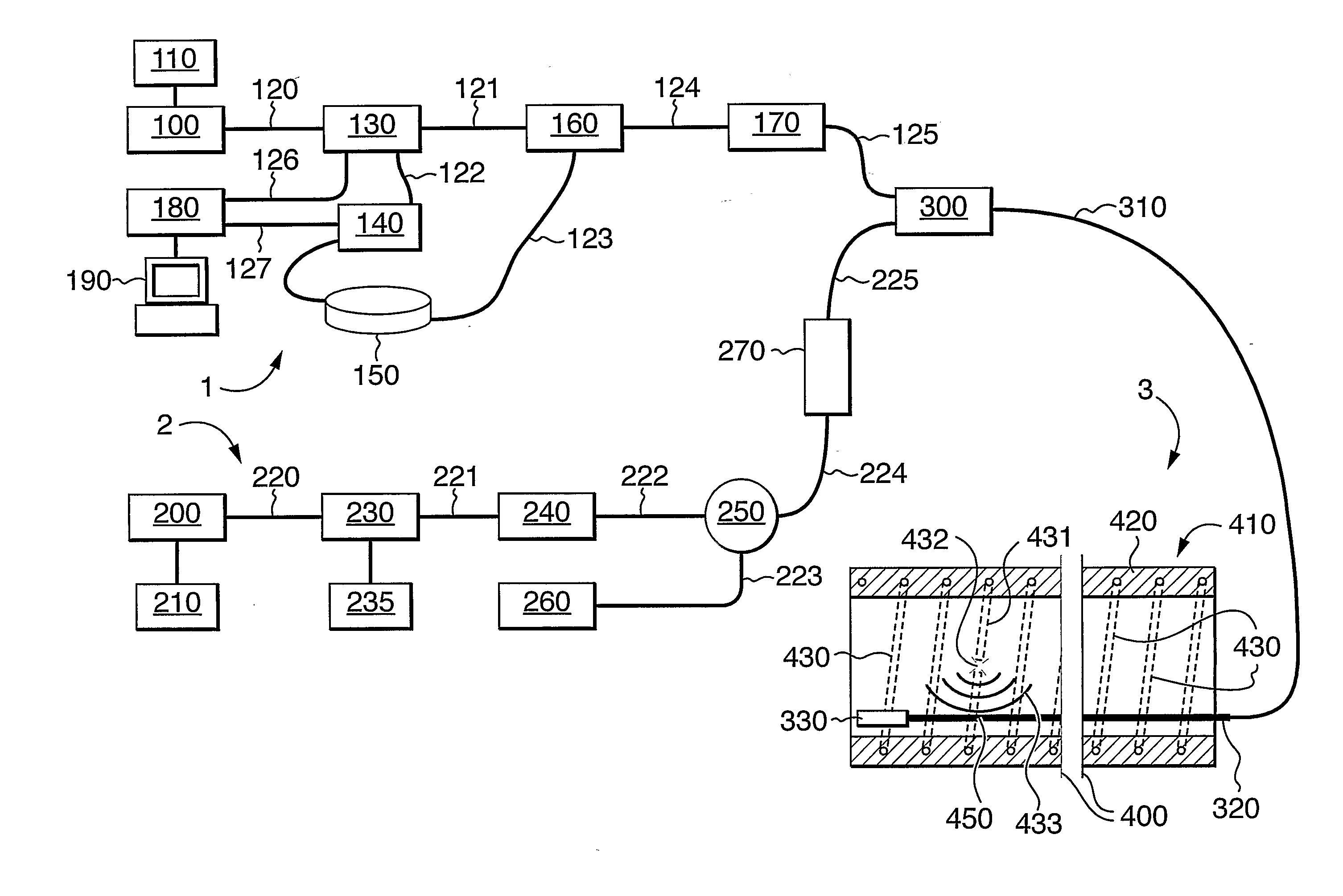
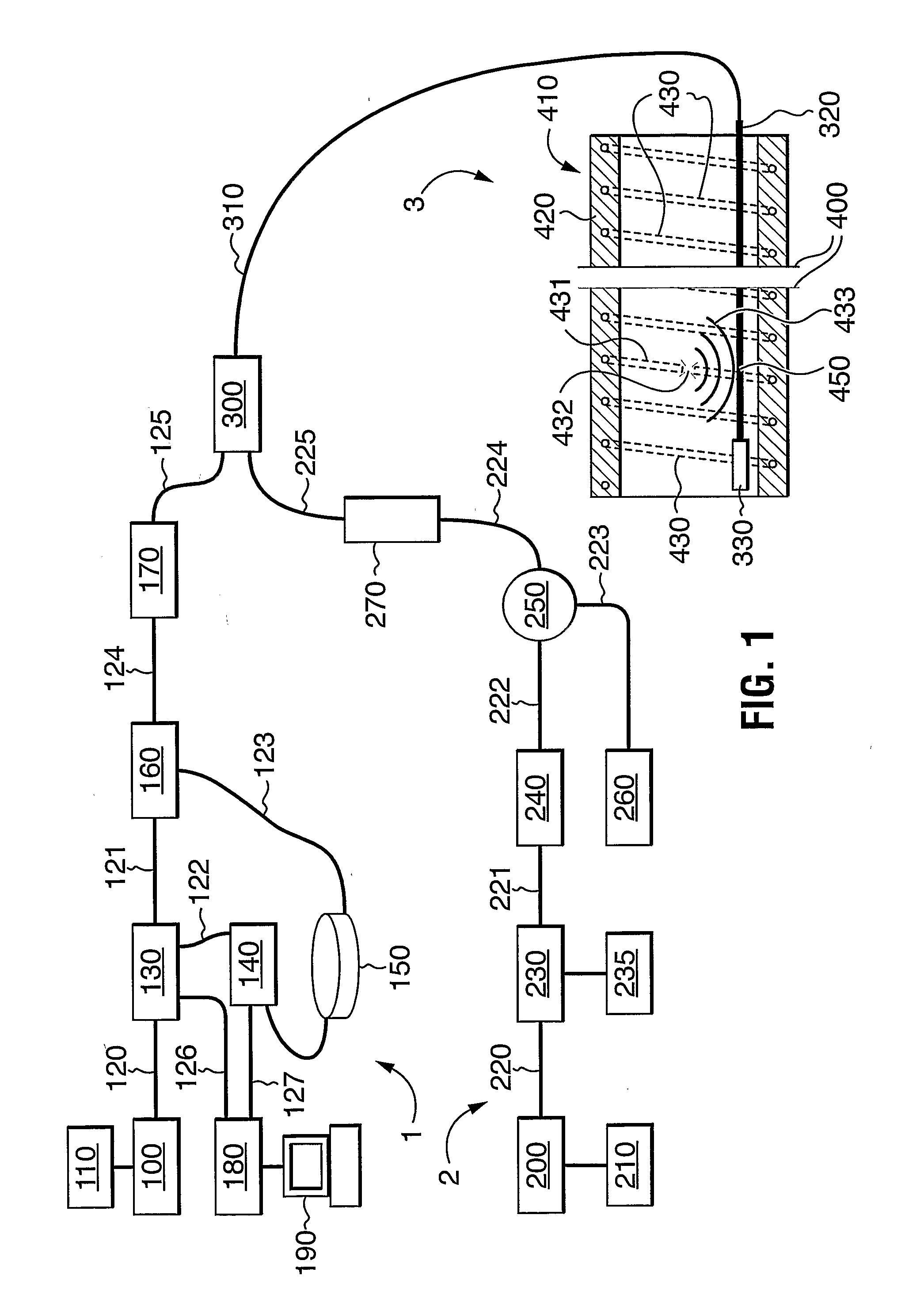
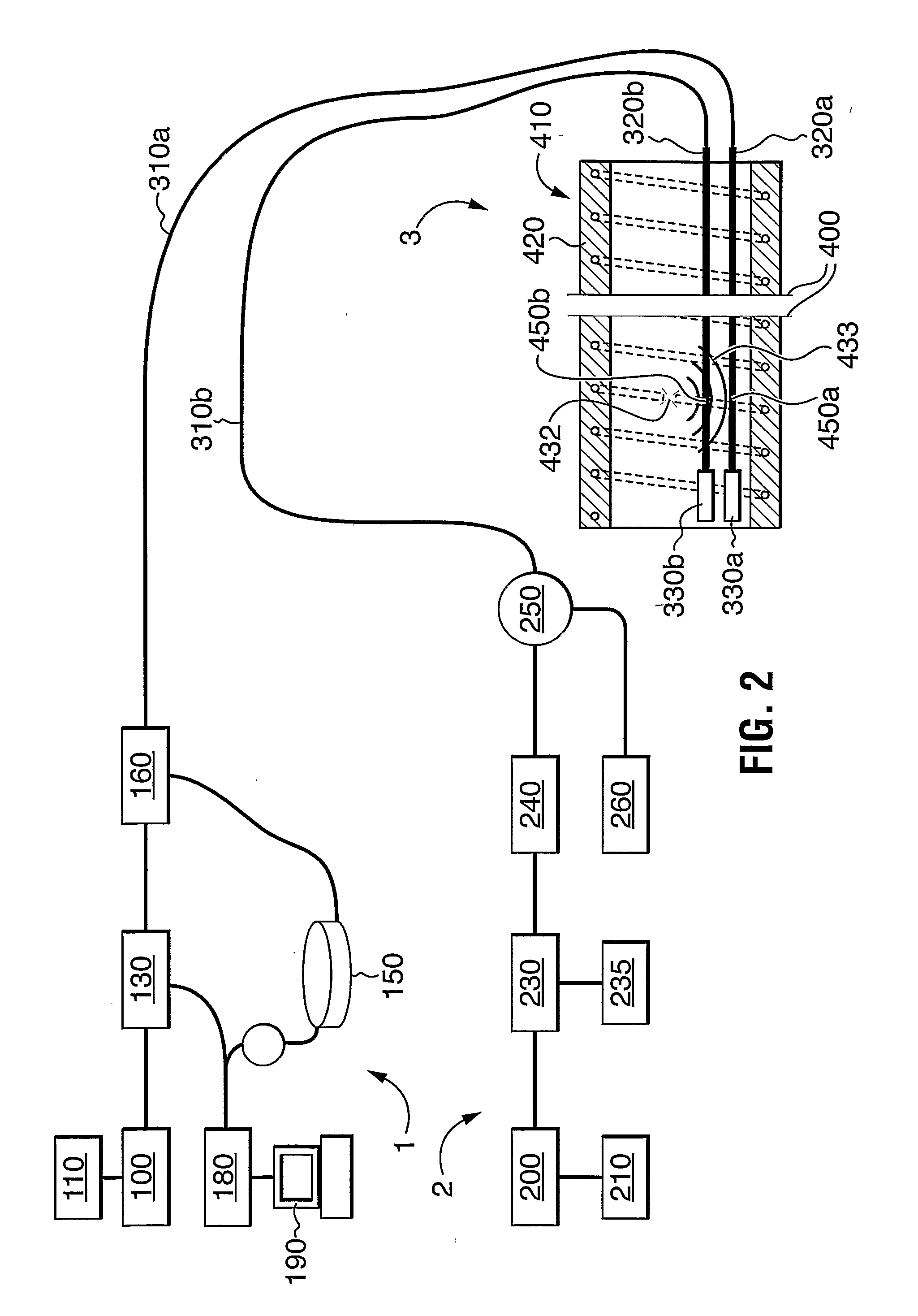
[0059] The use of the apparatus to determine events of interest will be described with respect to a test facility. The test facility was set up as FIG. 2. Sensor 320a had a sensor length of 10 kilometers, and was laid in a disused concrete water pipe. Sensors 320b and sensor 320a were two individual fibres within a single fibre optic cable, and were of the same length.

[0060] The interferometric sensor had a wavelength of 1310 nm. The pulsed OTDR sensor had a wavelength of 1550 nm, and was set to scan the length of the optical fibre every 10 milliseconds. Each scan took 200 microseconds. At least 750 scans of the OTDR were retained in memory. As each new scan was added, the oldest scan was dropped.

[0061] For the purpose of the test, it was determined that an event of interest would be any event that gave an analog signal of greater than 5 volts on an analog output in the particular test facility. The analog output was an arbitrary representation of disturbances in the interferometr...


PUM


Abstract

This invention uses an interferometric fibre optic sensor, particularly a Sagnac or Michelson interferometer, in a first fibre to monitor a sensing length of the first fibre and to detect disturbances. Signals indicating disturbances are classified as being of interest or not of interest, depending on predetermined criteria. Disturbances of interest can be, for example, the breaking of reinforcement wires in concrete pipe, the breaking of wires in suspension cables, a fire, a pipeline leak, or an intrusion. A location sensor system is used to determine the location of disturbances of interest, and to confirm the interferometer signal to reduce noise. The location sensor system is a fibre optic sensor, such as a phase OTDR sensor or a Brillouin effect sensor, which can detect the location of events it senses. It is present either in the first fibre or in a separate fibre laid adjacent the first fibre along its sensing length, as for example in the same optical cable.

Description

FIELD OF THE INVENTION [0001] This invention relates to a method of identifying a disturbance of interest using a fibre optic interferometer, and finding the location of the disturbance by using a separate sensor system. Disturbances of interest can be, for example, the breaking of reinforcement wires in concrete pipe, the breaking of wires in suspension cables, a pipeline leak, or an intrusion by human or vehicle. BACKGROUND TO THE INVENTION [0002] Fibre optic sensors exist which can monitor events over a distance of twenty kilometers or more, and which can be operated with relatively low power. Such fibre optic sensors can detect acoustic and seismic disturbances, such as for example the footfalls of an intruder near a monitored perimeter, the noises associated with intentional damage of a monitored piece of infrastructure such as an electrical or communications cable, the noise of a leak in a pipeline, or the breaking of a reinforcing wire in a concrete pipeline or a wire in a br...

Claims


Application Information

Patent Timeline
Patent Type & Authority Applications(United States)
IPC IPC(8): G01B9/02G01M3/04G01M3/38G01M11/08G01P13/00G08B13/186
CPCG01M3/047G08B13/186G01M11/083
Inventor PAULSON, PETER O.
Owner PURETECH VENTURES
Why Eureka
Try Eureka