Optical unit of a laser module

a laser module and optical unit technology, applied in the direction of instruments, semiconductor lasers, lenses, etc., can solve the problems of uncompetitive price of conventional laser modules installed in price-sensitive electronic products, inability to check the lighting status of laser diodes, and high material and assembly costs, so as to reduce material and assembly costs. , the effect of high material and assembly cos

Inactive Publication Date: 2007-10-25
ARIMA OPTOELECTRONICS
View PDF9 Cites 2 Cited by
  • Summary
  • Abstract
  • Description
  • Claims
  • Application Information

AI Technical Summary

Benefits of technology

[0006]It is a primary object of the invention to eliminate the above-mentioned drawbacks with respect to the high material and assembly cost and to provide an optical unit of a laser module having the advantage with respect to the reduction of the material and assembly cost.

Problems solved by technology

Therefore, the material and assembly cost is very high.
Thus, the conventional laser module that is installed in price-sensitive electronic products is uncompetitive in price.
As a result, it is not possible to check the lighting status of the laser diode 10 from the outside.
However, this kind of adjustment requires a lot of time.
This is regarded as impractical.

Method used


Image

  • Optical unit of a laser module
  • Optical unit of a laser module
  • Optical unit of a laser module

Examples


Embodiment Construction

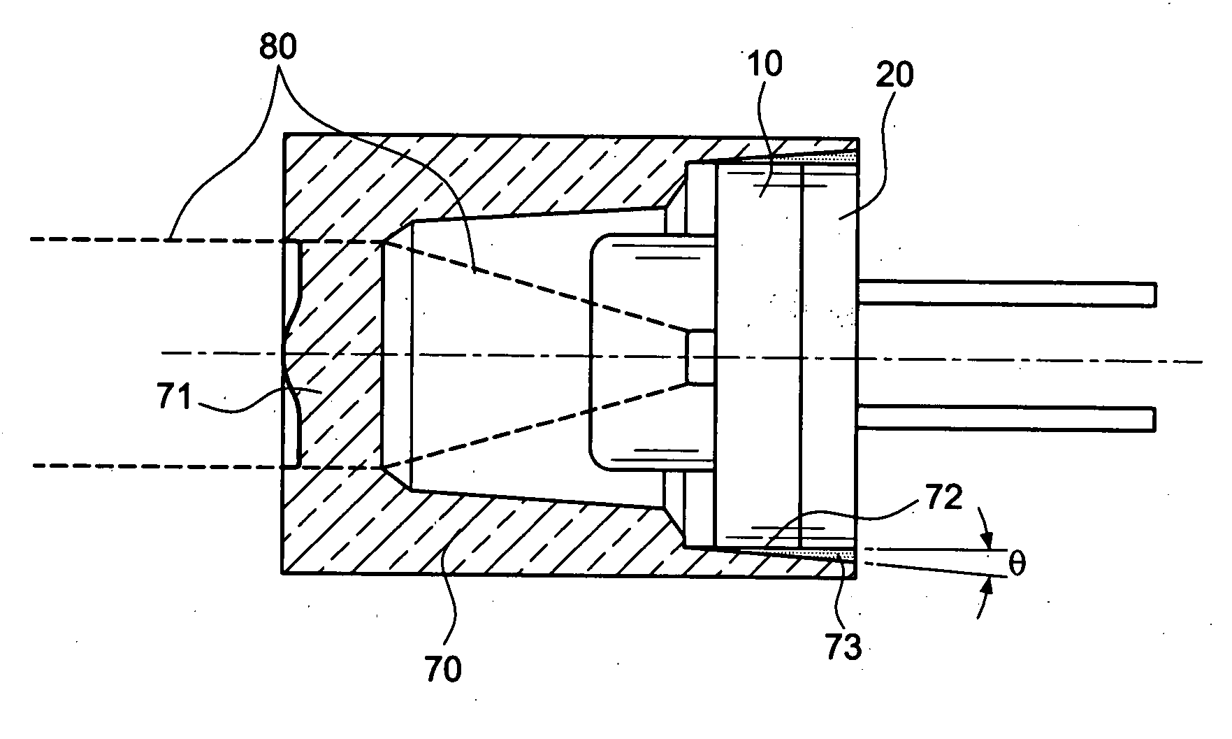
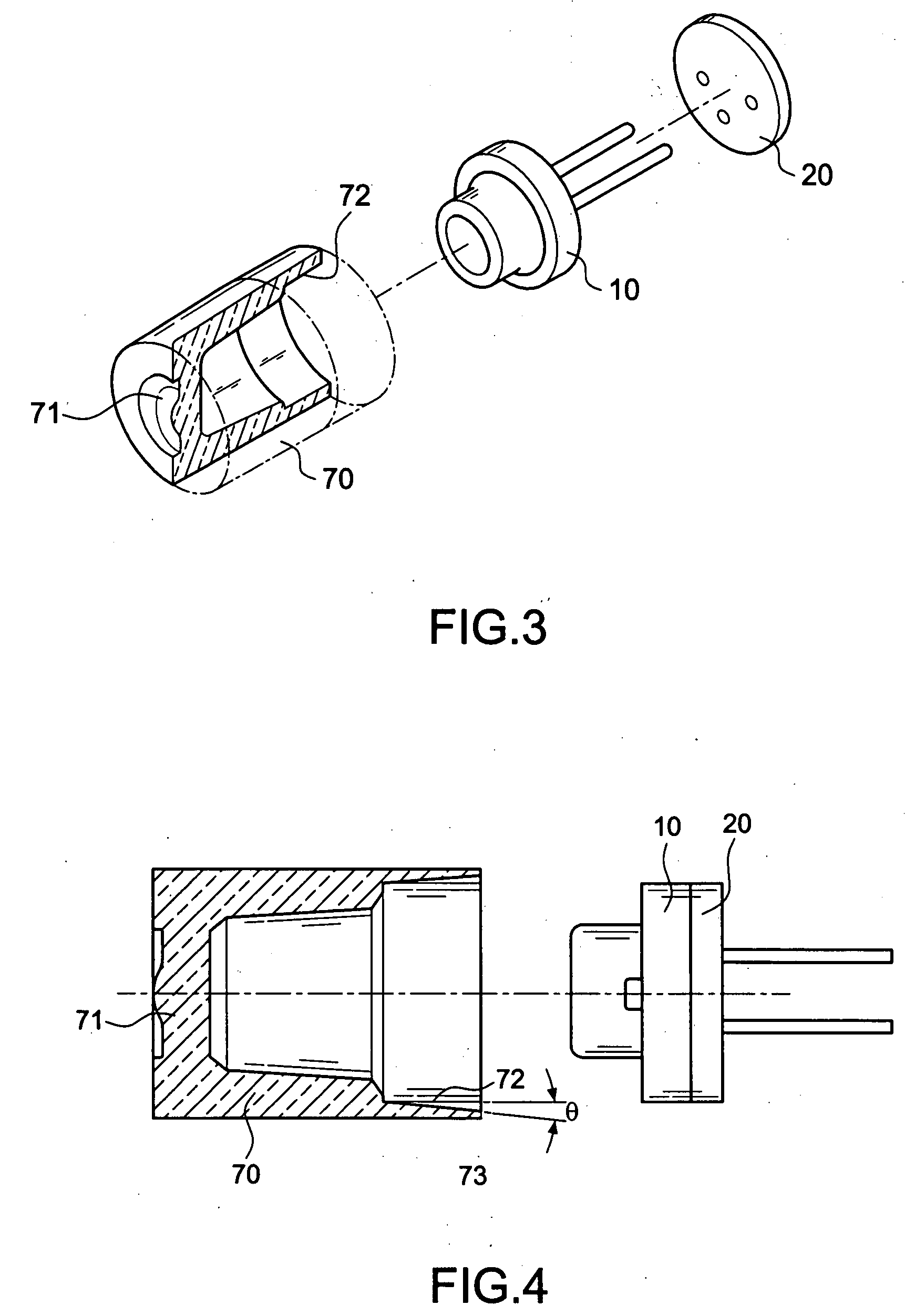
[0015]First of all, referring to FIGS. 2 and 3, the invention is installed at front end of a laser diode 10 of a drive circuit board 20. The invention includes a transparent sleeve 70 that is integrally injection molded from plastic material. An aspheric lens 71 is formed at the top of the transparent sleeve 70. The inner wall of the transparent sleeve 70 is provided with a focus adjusting slope 72 facing the laser diode 10. The focus adjusting slope 72 is outwardly inclined and has an angle (θ) with respect to the horizontal plane. As shown in FIG. 5, the conventional optical unit is so changed that it is injection molded out of transparent plastic material, thereby reducing the quantity of required components. Accordingly, the simplification of the components is ensured, thereby reducing the material and assembly cost. Moreover, the exterior allows a more complicated variation according to different requirements. Due to the transparency of the material, the examiner can learn from...


PUM


Abstract

An optical unit of a laser module is installed at front end of a laser diode of a drive circuit board. The optical unit includes a sleeve that is integrally injection molded from plastic material. Moreover, an optical lens is formed at the top of the sleeve. The inner wall of the sleeve is provided with a focus adjusting slope facing the laser diode. In this way, the problems of the prior art with respect to the high material and assembly cost can be resolved by the invention. In other words, the invention ensures the simplification of elements and the reduction of material and assembly cost.

Description

BACKGROUND OF THE INVENTION[0001]1. Field of the Invention[0002]The invention relates to an optical unit of a laser module, and more particularly to a design by use of an optical lens that is integrally injection molded.[0003]2. Description of the Related Art[0004]As shown in FIGS. 1 and 2, a conventional laser module includes a laser diode 10 disposed on a drive circuit board 20. An optical unit including a lens sleeve 30, an optical lens 40, an 0-ring 50 and a heat sink 60, is mounted on the laser diode 10. Most components of this conventional optical unit are made by metal processing. Therefore, the material and assembly cost is very high. Thus, the conventional laser module that is installed in price-sensitive electronic products is uncompetitive in price.[0005]Moreover, as shown in FIG. 2, the housing of the lens sleeve 30 and the heat sink 60 is made of metal like copper. As a result, it is not possible to check the lighting status of the laser diode 10 from the outside. In ad...

Claims


Application Information

Patent Timeline
Patent Type & Authority Applications(United States)
IPC IPC(8): G02B3/02
CPCH01S5/02288H01S5/02212H01S5/02253
Inventor LIN, CLARKOU, SZUTSUN-SIMON
Owner ARIMA OPTOELECTRONICS
Why Eureka
Try Eureka