
Supporting a 3D presentation

a three-dimensional image and support technology, applied in the field of supporting a three-dimensional image, can solve the problems of very apparent, low quality of perceived 3d image, minute inconsistencies, etc., and achieve the effect of reducing cropping losses, facilitating camera mounting, and increasing flexibility

Inactive Publication Date: 2007-10-25
NOKIA CORP
View PDF9 Cites 119 Cited by
  • Summary
  • Abstract
  • Description
  • Claims
  • Application Information

AI Technical Summary

Benefits of technology

[0043] It is an advantage of the invention that it allows for a more flexible camera mounting and thus for a greater variety in the concept creation of a device comprising two camera components providing the two images. The proposed image processing is actually suited to result in higher quality 3D images than an accurate camera alignment, which will never be quite perfect due to mechanical tolerances. The invention could even be used for generating 3D images based on images that have been captured consecutively by a single camera component. It has to be noted that the misalignment between the camera components or between two image capturing positions of a single camera component still needs to be within reasonable bounds so that the image plane overlap extends over a sufficiently large area to create the combined images after image shifting and cropping. It is further an advantage of the invention that it allows for an adjustment of disparities between two images, which are due to different properties of two camera components used for capturing the pair of images. It is further an advantage of the invention that it allows equally for an adjustment of disparities between two images, which have not been captured by camera components but are available from other sources.
[0044] In one embodiment of the invention, the image modifications are applied not only to one of the available images but evenly to each image in opposite directions. This approach has the advantage that cropping losses can be reduced and that the same center of image can be maintained.
[0045] The first calibration image and the second calibration image may be the same as or different from the first available image and the second available image, respectively.
[0046] The calibration images and the available images may further be obtained for instance by means of one or more camera components.
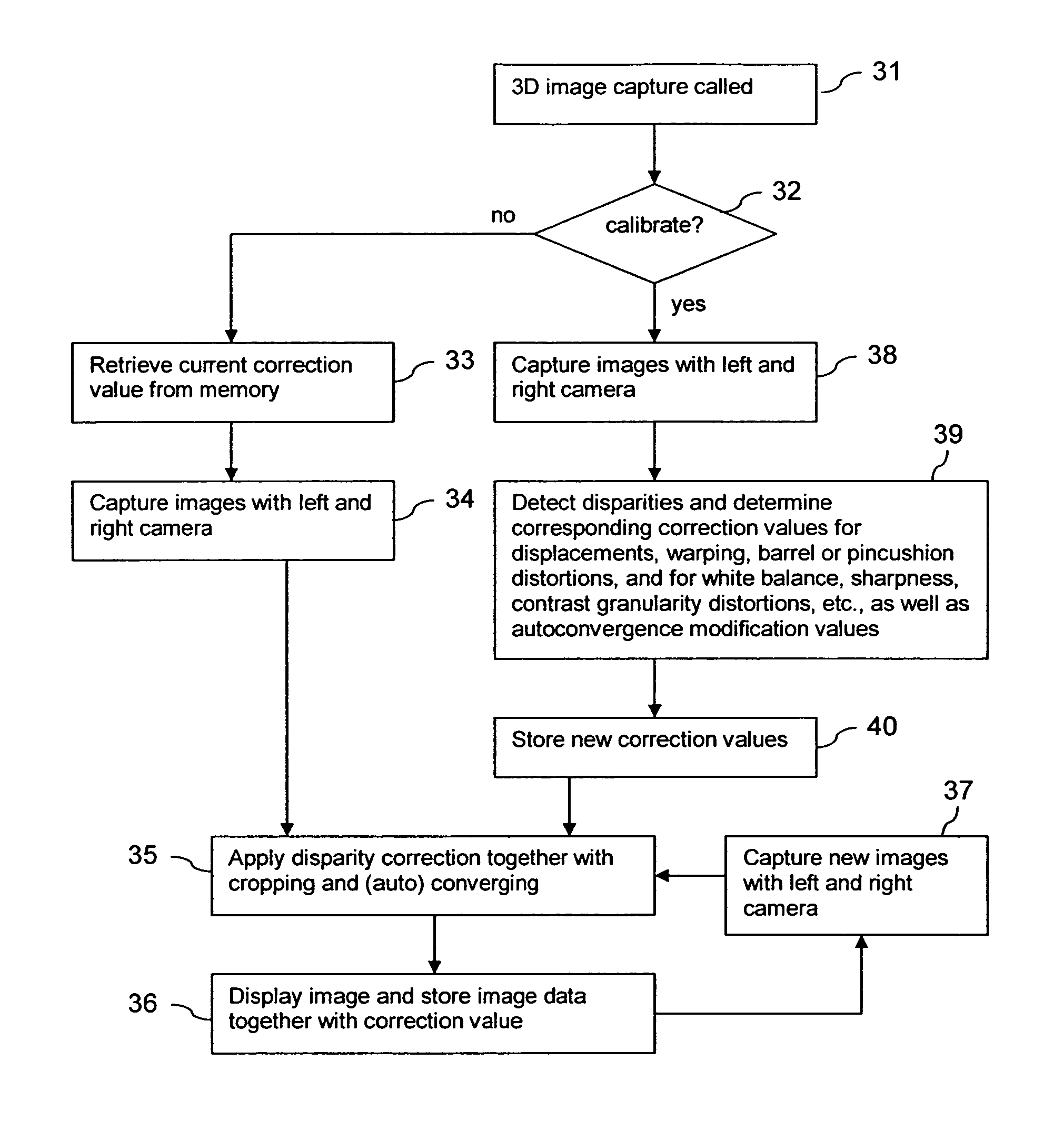
[0047] A respective first image may be captured for instance by a first camera component and a respective second image may be captured by a second camera component. The disparities that are detected for a specific image pair may be utilized for a modification of the same specific image pair or for a modification of subsequent images if the cameras do not move relative to each other in following image pairs. The calibration image pair based on which the disparity is detected may be for instance an image pair that has been captured exclusively for calibration purposes.
[0048] If a respective first image and a respective second image are captured by two aligned camera components, information on the determined set of disparities can also be stored for later use. In the case of two fixed camera components, it can be assumed that the disparities will stay the same for some time.

Problems solved by technology

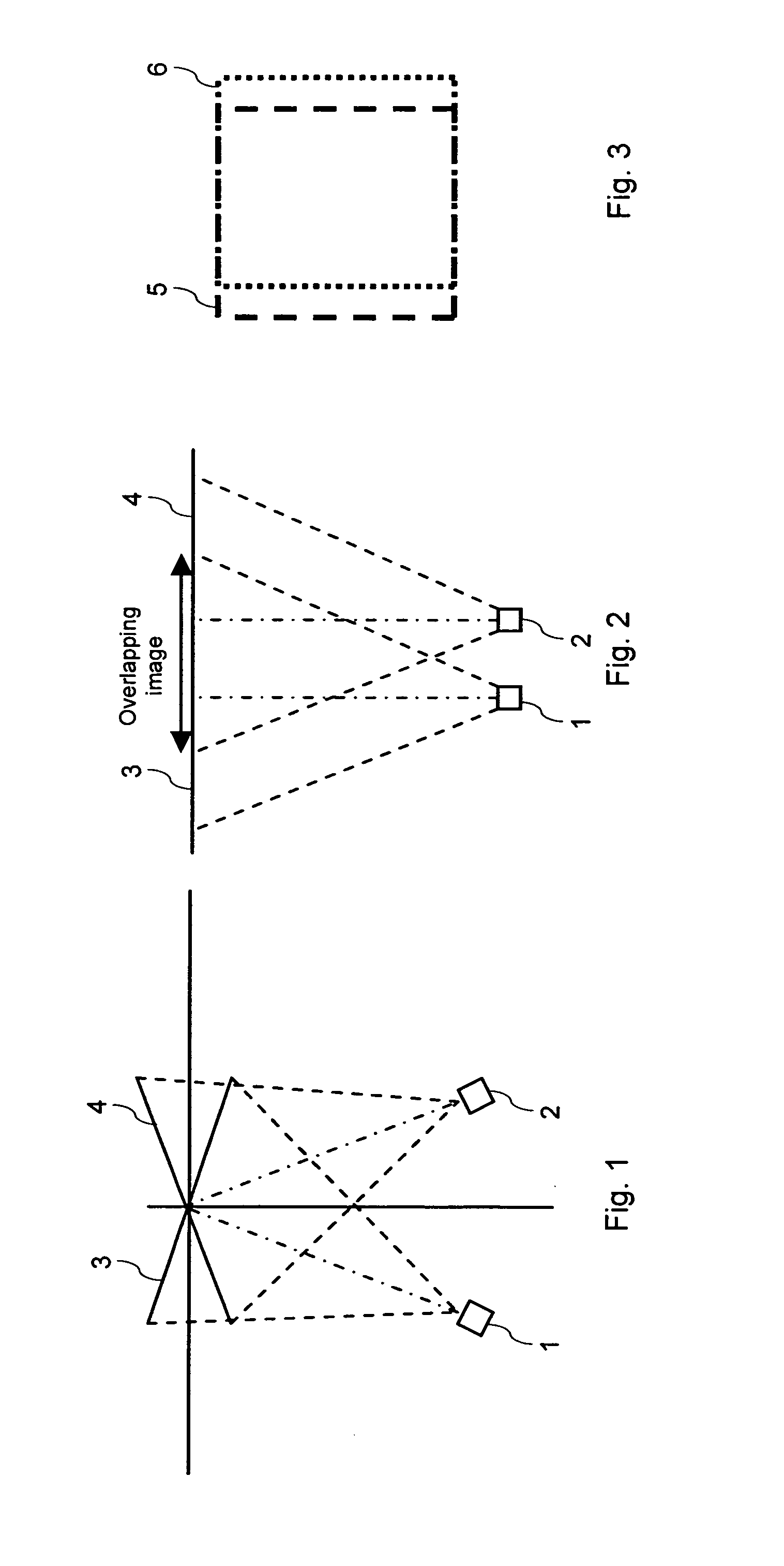
Cameras employed for capturing two-dimensional images for a 3D presentation, however, are not physically converged as in FIG. 1, since this would result in different image planes 3, 4 and thus projective warping of the resulting scene.
These minute inconsistencies, which would normally not be picked up in a 2D image, suddenly become very apparent when viewing the image pair in a 3D presentation.
Misalignments of this kind are unnatural for the human brain and result in a perceived 3D image of low quality.
An improved camera alignment will also be noticed to result in an increased ease of viewing, since even small misalignments may cause severe eye fatigue and nausea.
A large misalignment will render image fusion impossible.
Vertical differences generally cause eye fatigue, nausea and fusibility problems.
Horizontal differences result in artificially introduced disparities, which cause a warping of the perceived depth field.
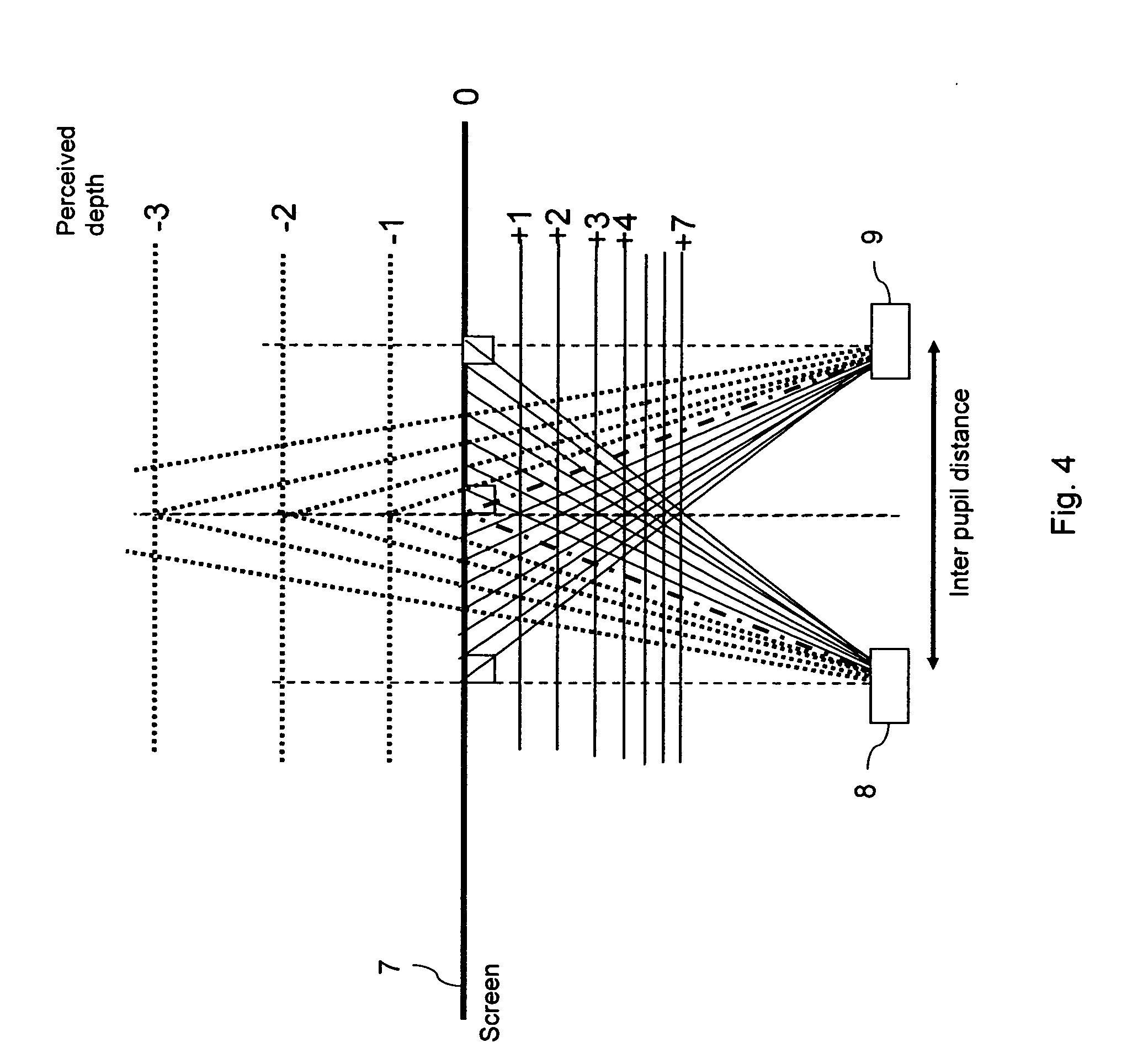
Uniform artificial horizontal displacements across the entire scene cause a shift in the depth of the entire scene, moving it in or out of the screen, due to the shifting of ZDP, FLP and BLP, placing objects outside of the comfortable virtual viewing space (CVVS) and hence causing eye strain and fusion problems.
Non-uniform horizontal shifts to parts of the image also cause sections of the image to be perceived at the wrong depth relative to the depth of the rest of the scene, giving an unnatural feel to the scene and so losing the realism of the scene.
Such Y displacements are undesirable, as they cause each eye to perceive the scene at a different height, hence causing fusion problems.
As a result, the distance from each object in the scene changes, with the same horizontal and vertical offset from the camera, hence causes a chance in the angle of the light ray, causing a moving of the X and y position of each object and a scaling of each object in the scene.
This causes convergence problems and also moves the ZDP backwards.
As a result, the height of objects on the lateral edges of the screen appears to be different for each eye, hence the different vertical position causes eye strain.
Moreover, the non-linearity of the X axis causes a change in perceived depth, and the middle of the scene will hence appear closer to the observer then the side of the scene, causing flat walls to be perceived as bent.
As a result, fusion problems can occur.
In extreme situations, it could cause a greater negative screen disparity than the human eyes can cope with, forcing the eyes to go wall eyed, meaning that the eyes are diverged from parallel and are looking for instance at opposite walls, which is unnatural as human eyes are not designed to diverge from parallel.
This implies a vertical shift, a slight non-linearity along the vertical axis and keystone distortion, which results in a horizontal shift in the corners of the image causing a warping of the depth field.
Such accurate arrangements require tight tolerances for camera mountings, which limits the device concept flexibility.
Moreover, even in an accurately set system there will inevitably occur some camera misalignment increasing eye fatigue.
Misalignments can even occur in rigid candy bar devices, for instance when they are dropped or due to a heating of the device.
The tight 3D camera misalignment tolerances thus make the production of devices, which allow capturing images for a 3D presentation, rather complicated.
Meeting the requirements is even more difficult with devices, for which it is desirable to be able to have rotating cameras for tele-presence applications.
In addition to the physical misalignment differences between cameras capturing an image pair, there may also be other types of mismatching between the images due to different camera properties, for example a mismatch of white balance, sharpness, granularity and various other image factors.
Moreover, the employed lenses may cause distortions between a pair of images.
Therefore, lens distortions that are non-uniform across the image will become apparent, as the left and right image will experience the distortions differently.

Method used


Image

  • Supporting a 3D presentation
  • Supporting a 3D presentation
  • Supporting a 3D presentation

Examples


Embodiment Construction

[0095]FIG. 9 is a schematic block diagram of an exemplary apparatus, which allows compensating for a misalignment of two cameras of the apparatus by means of an image adaptation, in accordance with a first embodiment of the invention.

[0096] By way of example, the apparatus is a mobile phone 10. It is to be understood that only components of the mobile phone 10 are depicted, which are of relevance for the present invention.

[0097] The mobile phone 10 comprises a left hand camera 11 and a right hand camera 12. The left hand camera 11 and the right hand camera 12 are roughly aligned at a predetermined distance from each other. That is, when applying the co-ordinate system of FIG. 6, they have Y, Z, θX, θY and θZ values close to zero. Only their X-values differ from each other approximately by a predetermined amount. Both cameras 11, 12 are linked to a processor 13 of the mobile phone 10.

[0098] The processor 13 is adapted to execute implemented software program code. The implemented s...


PUM


Abstract

For supporting a three-dimensional presentation on a display, which presentation combines at least a first available image and a second available image, differences between a first calibration image and a second calibration image are detected. At least one of a first available image and a second available image are then modified to approach desired disparities between the first available image and the second available image based on the detected disparities between the first calibration image and the second calibration image.

Description

FIELD OF THE INVENTION [0001] The invention relates to a method for supporting a three-dimensional presentation on a display, which presentation combines at least a first available image and a second available image. The invention relates equally to a corresponding apparatus and to a corresponding software program product. BACKGROUND OF THE INVENTION [0002] Stereoscopic displays allow presenting an image that is perceived by a user as a three-dimensional (3D) image. To this end, a stereoscopic display directs information from certain sub-pixels of an image in different directions, so that a viewer can see a different picture with each eye. If the pictures are similar enough, the human brain will assume that the viewer is looking at a single object and fuse matching points on the two pictures together to create a perceived single object. The human brain will match similar nearby points from the left and right eye input. Small horizontal differences in the location of points will be r...

Claims


Application Information

Patent Timeline
Patent Type & Authority Applications(United States)
IPC IPC(8): G06K9/00
CPCH04N13/0425H04N13/0022H04N13/128H04N13/327
Inventor POCKETT, LACHLAN
Owner NOKIA CORP
Learn More