Ancillary oil pumping for gear box assembly

a gear box and auxiliary oil technology, applied in the direction of machines/engines, gearing details, liquid fuel engines, etc., can solve the problems of premature wear or failure, difficult to ensure adequate lubrication supply in such applications, and disadvantages, etc., to achieve effective lubrication of specified locations and simple pumping

Active Publication Date: 2007-11-01
ARVINMERITOR TECH
View PDF10 Cites 32 Cited by
  • Summary
  • Abstract
  • Description
  • Claims
  • Application Information

AI Technical Summary

Benefits of technology

[0011] The subject invention provides a simple pumping mechanism that effectively lubricates specified locations within a gear box assembly. These and...

Problems solved by technology

This method can present difficulties with applications that have large vertical separation between gears, such as in inverted portal axle and transfer case applications.
Ensuring an adequate supply of lubrication in such applications is often difficult to achieve.
Thus, not all of the gear box components receive a consistent and reliable su...

Method used


Image

  • Ancillary oil pumping for gear box assembly
  • Ancillary oil pumping for gear box assembly
  • Ancillary oil pumping for gear box assembly

Examples


Embodiment Construction

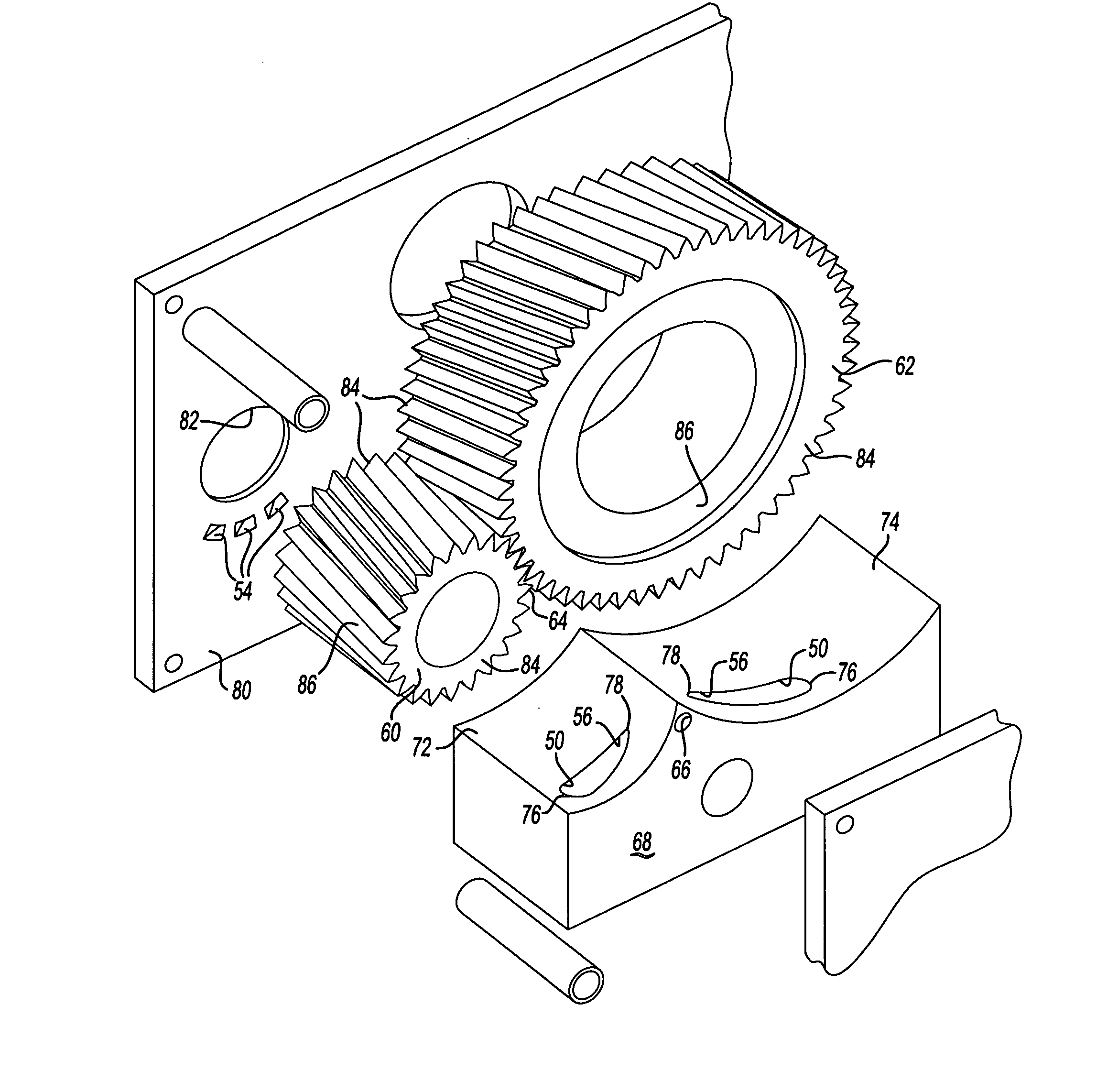
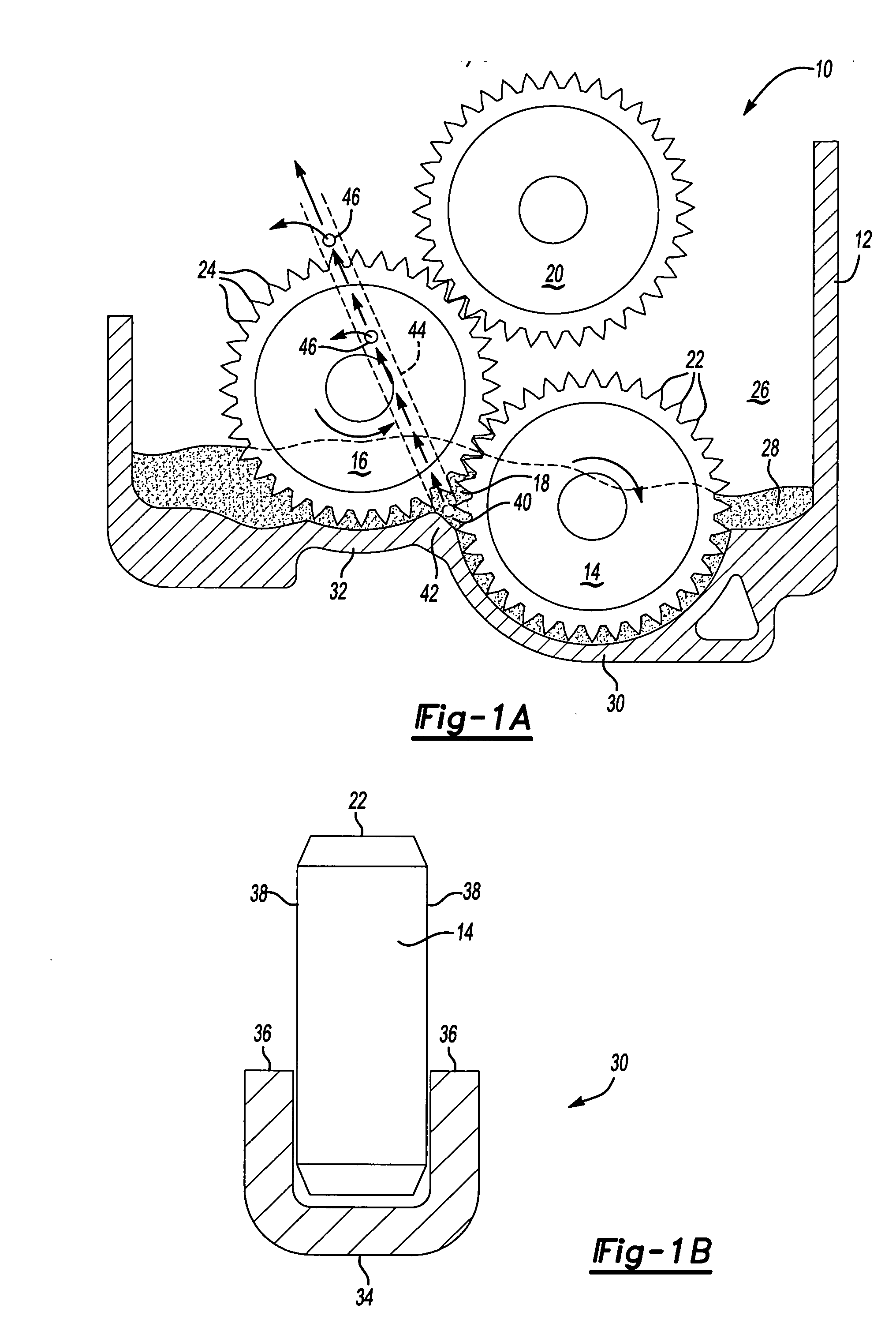
[0026]FIG. 1A shows a gear box assembly 10 including a housing 12, a drive gear 14, and a driven gear 16 in meshing engagement with the drive gear 14 at a contact point 18. The driven gear 16 can be an output gear for driving a vehicle component, or can be an idler or intermediary gear that is used to drive another output gear 20.

[0027] The drive gear 14 includes a gear body with a plurality of drive gear teeth 22 formed about an outer circumference of the drive gear 14. The driven gear 16 includes a gear body with a plurality of driven gear teeth 24 formed about the outer circumference of the driven gear. The plurality of drive gear teeth 22 are in direct meshing engagement with the plurality of driven gear teeth 24.

[0028] The housing 12 defines an inner cavity 26 that holds lubrication fluid 28, such as oil for example. The drive 14 and driven 16 gears are mounted within the inner cavity 26 and are preferably positioned such that at least a portion of one of the gear bodies is i...


PUM


Abstract

A gear box assembly as used in an inverted portal axle or transfer case includes a drive gear and at least one driven gear in meshing engagement with the drive gear at a contact point. A gear housing closely surrounds portions of an outer circumference of the drive and driven gears to form a baffle area. The gear housing includes an discharge orifice that is located near the contact point and a fluid gallery that extends from the discharge orifice to other locations within the gear housing. As the drive gear drives the driven gear, fluid is pumped into the discharge orifice and through the fluid gallery to fluid outlets positioned at desired locations to lubricate other gear box components. Radial inlets with elongated chamfers and stator vanes can be formed within the gear housing to draw air ingested during pumping away from the discharge orifice. Additionally, a bypass loop can be used to scavenge unwanted air ingested into meshing gear teeth.

Description

TECHNICAL FIELD [0001] A gear box assembly includes a gear set with a gear housing having an orifice formed near a gear contact point such that fluid is pumped by the gear set through the orifice to selectively lubricate other gear box components within the gear housing. BACKGROUND OF THE INVENTION [0002] Gear boxes are used in many different drivetrain applications within a vehicle, including transfer case and inverted portal axle applications. The gear boxes include components such as gears, bearings, thrust washers, shafts, etc. that are housed within a gear housing. These components need to be sufficiently lubricated during operation to minimize fatigue and wear. [0003] Traditionally, lubrication has been provided by a “splash” lubrication method. In the “splash” lubrication method oil is flung or splashed about within the gear housing as a result of various movements of the components in the gear box. This method can present difficulties with applications that have large vertic...

Claims


Application Information

Patent Timeline
IPC IPC(8): F16H57/02
CPCF16H57/0421Y10T74/2186Y10T74/19991F16H57/0434
Inventor HAYES, BRIAN DAVIDBRILL, LAWRENCE DOYLE
Owner ARVINMERITOR TECH
Why Eureka
Try Eureka