
Motorcycle

a technology for motorcycles and crankshafts, applied in the direction of crankshaft transmission, bicycle equipment, friction roller based transmission, etc., can solve the problems of complex internal construction of clean rooms, decrease in durability of v-belts, etc., and achieve the effect of preventing dust invasion and simple construction

Inactive Publication Date: 2007-11-01
YAMAHA MOTOR CO LTD
View PDF14 Cites 13 Cited by
  • Summary
  • Abstract
  • Description
  • Claims
  • Application Information

AI Technical Summary

Benefits of technology

The invention provides a motorcycle with a rear tire and a belt chamber for transmitting driving force to the rear tire. A duct introduces outside air into the belt chamber, and a wall separates the seat and the rear tire to prevent dust and sludge from entering the chamber. The invention prevents dust and sludge from entering the belt chamber, ensuring a stable operating state of the belt. Other features include a side cover, a side intake port, an engine, a body frame, a fuel tank, a cover filler, a duct with an elliptical cross-section, a bellows, a sealing member, and an interlocking member.

Problems solved by technology

However, the V-belt generates heat due to friction with a drive pulley at the time of running, which decreases the V-belt in durability.
However, since the outside-air intake port is arranged in a low position of the vehicle body and in the vicinity of a front wheel, the internal construction of the clean room must be complex in order to prevent invasion of dust that is splashed by the front wheel.
However, since the outside-air intake port of the air cleaner is arranged just above a rear wheel, dust splashed by the rear wheel is mixed with the air sucked into the intake port, making it necessary to frequently perform maintenance of the air cleaner.

Method used


Image

  • Motorcycle
  • Motorcycle
  • Motorcycle

Examples


Embodiment Construction

[0037] An embodiment of the invention is now described with reference to the drawings. The invention is not limited to the following embodiment.

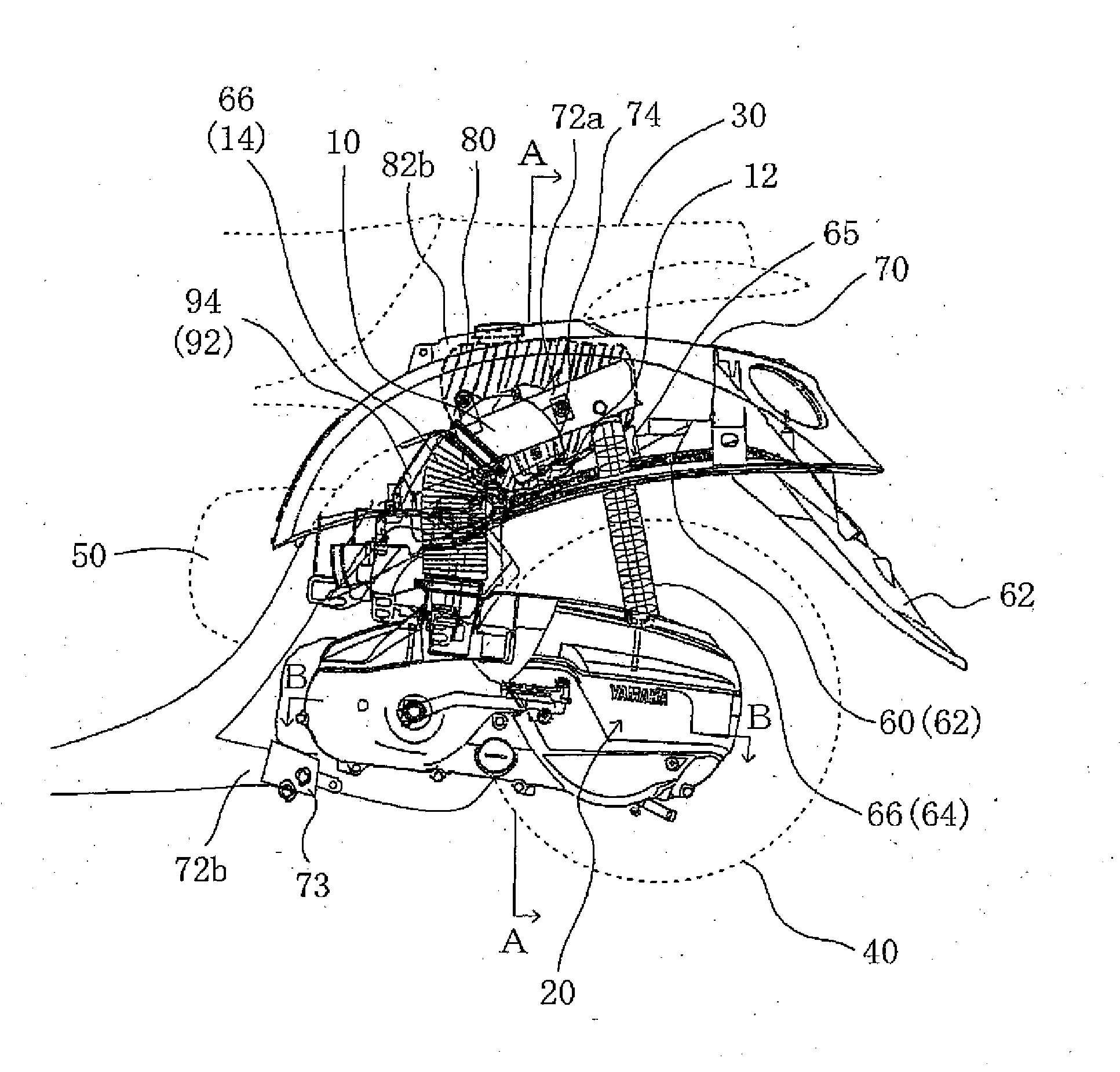
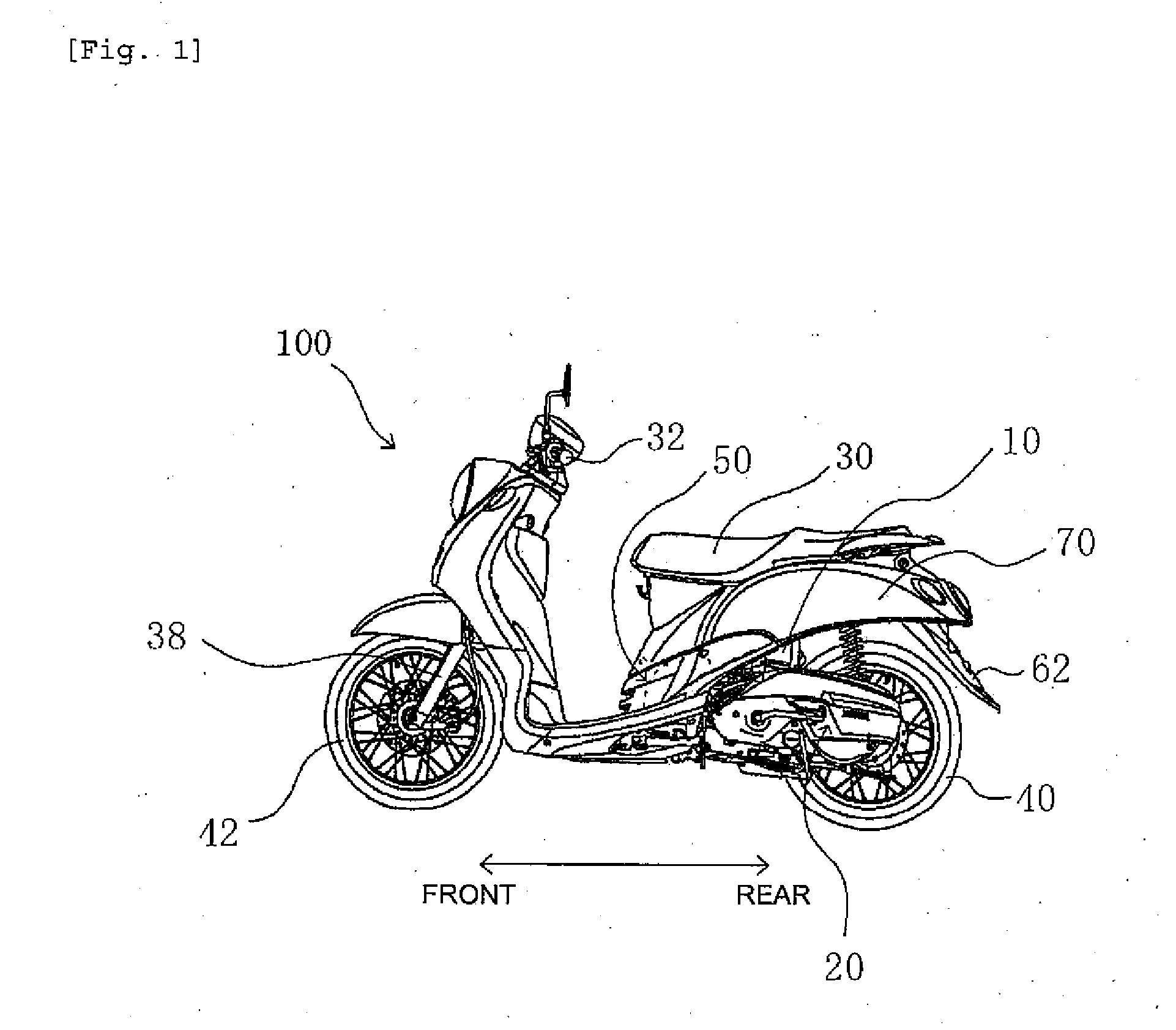
[0038] A motorcycle 100 according to the embodiment of the invention is illustrated in FIG. 1. Motorcycle 100 includes a seat 30, a handle 32, a front tire 42, a rear tire 40 and an engine 50.

[0039] Seat 30 is arranged centrally in a longitudinal direction of a vehicle body and handle 32 is forward of seat 30. A front fork 38 extending forwardly and downwardly from handle 32 supports front tire 42. A manipulating force applied by a rider to handle 32 is transmitted to front tire 42 via front fork 38. A traveling direction of motorcycle 100 is determined by changing a direction of front tire 42.

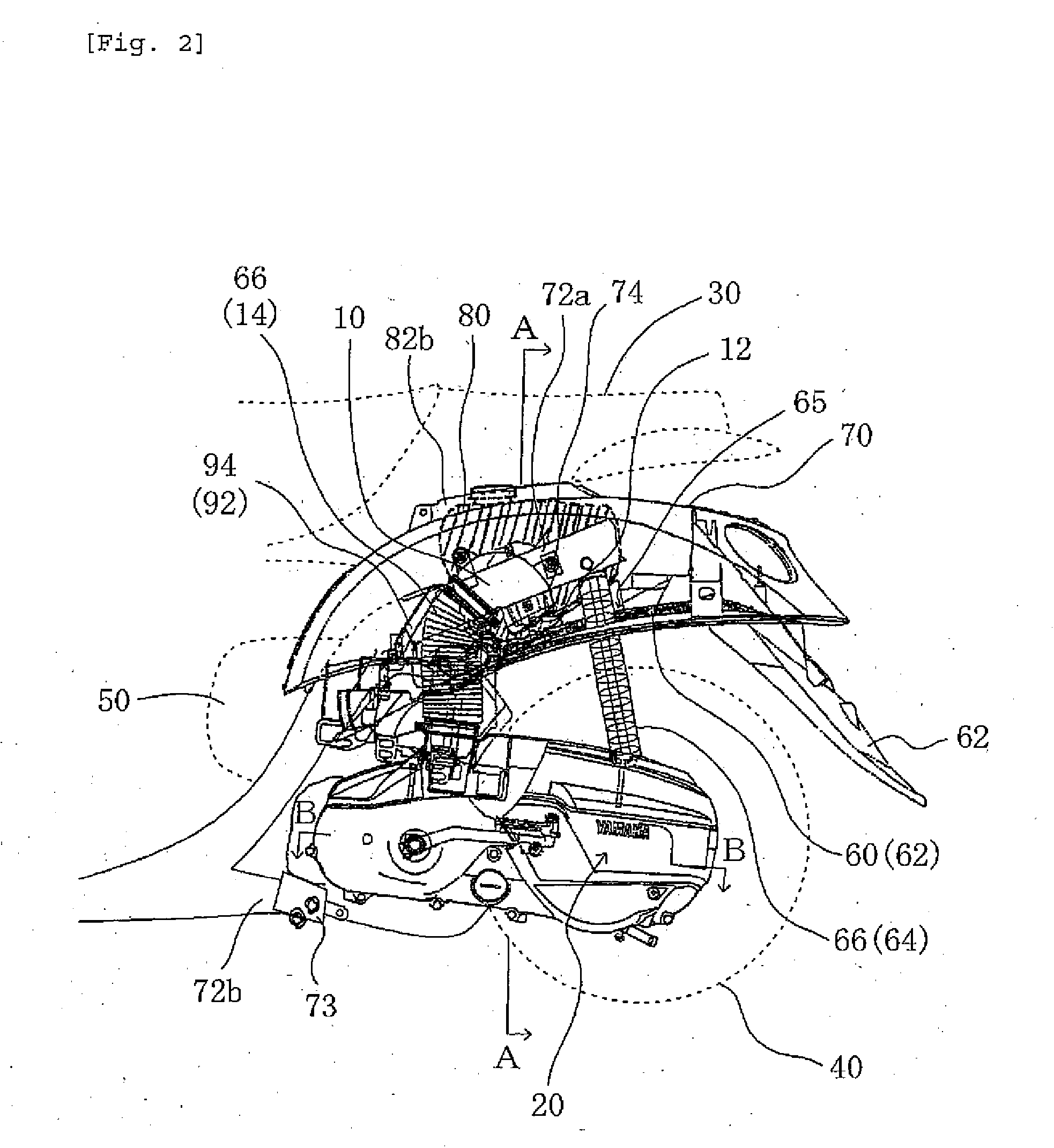
[0040] Engine 50 is below seat 30 and rear tire 40 is rearward of engine 50. A belt (not shown) interposed between engine 50 and rear tire 40 transmits power generated by engine 50 to drive rear tire 40. The belt is a V-belt used as a continuously v...


PUM


Abstract

A motorcycle has a duct that is simple in construction to introduce cooling air into a belt chamber while simultaneously preventing invasion of dust, etc. into the belt chamber. A rear fender defines a wall that separates the seat and a rear tire. An outside-air intake port of the duct is arranged in a space formed between the seat and the wall.

Description

RELATED APPLICATIONS [0001] This application claims the benefit of priority under 35 USC 119 of Japanese patent application no. 2006-125796, filed on Apr. 28, 2006, and Japanese patent application no. 2007-095127, filed on Mar. 30, 2007, which applications are hereby incorporated by reference in their entireties. BACKGROUND OF THE INVENTION [0002] 1. Field of the Invention [0003] The present invention relates to a motorcycle, and more particularly to a motorcycle provided with a duct through which air is led to a belt chamber. [0004] 2. Description of Related Art [0005] Some motorcycle transmissions use a V-belt, which is simple in construction and inexpensive. Since a V-belt may slip when dust and sludge adhere thereto, the V-belt is accommodated in a belt chamber to prevent adherence of dust, sludge, etc. thereto. However, the V-belt generates heat due to friction with a drive pulley at the time of running, which decreases the V-belt in durability. And, when the V-belt is accommod...

Claims


Application Information

Patent Timeline
Patent Type & Authority Applications(United States)
IPC IPC(8): B60K11/00B62J15/00B62J99/00B62J23/00B62J35/00B62K25/20B62M7/12B62M9/06
CPCB62K2202/00F16H57/04B62M7/12B62J50/30
Inventor MATSUZAWA, TORAO
Owner YAMAHA MOTOR CO LTD
Learn More